CAN COMMUNICATION SYSTEM(w/ Central Gateway ECU) Check Bus 2 Lines for Short Circuit
DESCRIPTION
There may be a short circuit between the bus 2 main lines and/or CAN branch lines when the resistance between terminals 18 (CA4H) and 17 (CA4L) of the central gateway ECU is below 54 Ω.
| Symptom | Trouble Area |
|---|---|
| Resistance between terminals 18 (CA4H) and 17 (CA4L) of central gateway ECU is below 54 Ω. |
|
-
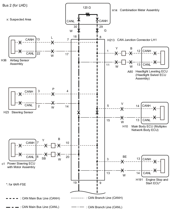
*: for 6AR-FSE
WIRING DIAGRAM
CAUTION / NOTICE / HINT
Note
-
Before measuring the resistance of the CAN bus, turn the engine switch off and leave the vehicle for 1 minute or more without operating the key or any switches, or opening or closing the doors. After that, disconnect the cable from the negative (-) battery terminal and leave the vehicle for 1 minute or more before measuring the resistance.
-
After turning the engine switch off, waiting time may be required before disconnecting the cable from the negative (-) battery terminal. Therefore, make sure to read the disconnecting the cable from the negative (-) battery terminal notices before proceeding with work Click here.
-
Because the order of diagnosis is important to allow correct diagnosis, make sure to begin troubleshooting using How to Proceed with Troubleshooting when CAN communication system related DTCs are output Click here.
-
After performing repairs, perform the DTC check procedure and confirm that the DTCs are not output again.
-
DTC check procedure: Drive the vehicle at a speed of 36 km/h (22 mph) or more for 5 minutes or more.
-
After the repair, perform the CAN bus check and check that all the ECUs and sensors connected to the CAN communication system are displayed Click here.
-
If the main body ECU (multiplex network body ECU) is replaced, refer to Service Bulletin.
Tech Tips
-
Operating the engine switch, any other switches or a door triggers related ECU and sensor communication on the CAN. This communication will cause the resistance value to change.
-
Even after DTCs are cleared, if a DTC is stored again after driving the vehicle for a while, the malfunction may be occurring due to vibration of the vehicle. In such a case, wiggling the ECUs or wire harness while performing the inspection below may help determine the cause of the malfunction.
-
Connectors that connect to the CAN junction connector can be distinguished by the color of their CAN bus lines. When the connectors have been disconnected from the CAN junction connector, reconnecting the connectors to non-original positions on the CAN junction connector does not affect system performance. However, it is preferred to reconnect the connectors to their original positions to avoid negative effects on the wiring such as tension on the wiring harnesses, and to make future maintenance easier.
PROCEDURE
-
CHECK FOR SHORT IN CAN BUS LINES (CENTRAL GATEWAY ECU)
-
Disconnect the cable from the negative (-) battery terminal.
-
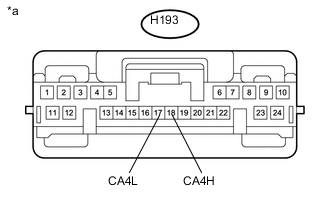
Disconnect the H193 central gateway ECU connector.
-
Measure the resistance according to the value(s) in the table below.
Standard Resistance Tester Connection Condition Specified Condition H193-18 (CA4H) - H193-17 (CA4L) Cable disconnected from negative (-) battery terminal 54 to 69 Ω Text in Illustration *a Front view of wire harness connector
(to Central Gateway ECU)
Result Result Proceed to OK A NG (for LHD) B NG (for RHD) C
A 
REPLACE CENTRAL GATEWAY ECU Click here
C 
CHECK FOR SHORT IN CAN BUS LINES (CENTRAL GATEWAY ECU BRANCH LINE) Click here
B 
-
-
CHECK FOR SHORT IN CAN BUS LINES (CENTRAL GATEWAY ECU BRANCH LINE)
-
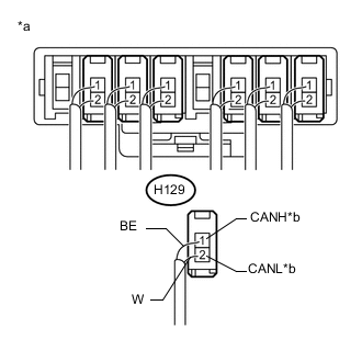
Text in Illustration *a Rear view of wire harness connector
(to CAN Junction Connector RH1)
*b to Central Gateway ECU Disconnect the H129 central gateway ECU branch line connector.
Tech Tips
-
Connectors that connect to the CAN junction connector can be distinguished by the color of their CAN bus lines.
-
Reconnecting the connectors to non-original positions on the CAN junction connector does not affect system performance. However, it is preferred to reconnect the connectors to their original positions to avoid negative effects on the wiring such as tension on the wiring harnesses, and to make future maintenance easier.
-
-
Text in Illustration *a Front view of wire harness connector
(to Central Gateway ECU)
Measure the resistance according to the value(s) in the table below.
Standard Resistance Tester Connection Condition Specified Condition H193-18 (CA4H) - H193-17 (CA4L) Cable disconnected from negative (-) battery terminal 1 MΩ or higher
NG
REPAIR OR REPLACE CAN BRANCH LINE CONNECTED TO CENTRAL GATEWAY ECU
OK
-
-
CHECK FOR SHORT IN CAN BUS LINES (CAN J/C LH1)
-
Reconnect the H129 central gateway ECU branch line connector.
-
Disconnect the H213 CAN junction connector LH1.
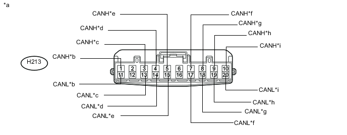
Text in Illustration *a Front view of wire harness connector
(to CAN Junction Connector LH1)
*b to Headlight Leveling ECU (Headlight Swivel ECU Assembly) *c to Engine Stop and Start ECU
(for 6AR-FSE)
*d to Steering Sensor *e to Main Body ECU (Multiplex Network Body ECU) *f to Airbag Sensor Assembly *g to Combination Meter Assembly *h to CAN Junction Connector RH1 *i to Power Steering ECU with Motor Assembly - - -
Measure the resistance according to the value(s) in the table below.
Standard Resistance Tester Connection Condition Specified Condition Connected to H213-1 (CANH) - H213-11 (CANL) Cable disconnected from negative (-) battery terminal 200 Ω or higher Headlight leveling ECU (headlight swivel ECU assembly) H213-3 (CANH) - H213-13 (CANL) Cable disconnected from negative (-) battery terminal 200 Ω or higher Engine stop and start ECU* H213-4 (CANH) - H213-14 (CANL) Cable disconnected from negative (-) battery terminal 200 Ω or higher Steering sensor H213-5 (CANH) - H213-15 (CANL) Cable disconnected from negative (-) battery terminal 200 Ω or higher Main body ECU (multiplex network body ECU) H213-7 (CANH) - H213-17 (CANL) Cable disconnected from negative (-) battery terminal 200 Ω or higher Airbag sensor assembly H213-8 (CANH) - H213-18 (CANL) Cable disconnected from negative (-) battery terminal 108 to 132 Ω Combination meter assembly H213-9 (CANH) - H213-19 (CANL) Cable disconnected from negative (-) battery terminal 108 to 132 Ω CAN junction connector RH1 H213-10 (CANH) - H213-20 (CANL) Cable disconnected from negative (-) battery terminal 200 Ω or higher Power steering ECU with motor assembly *: for 6AR-FSE
Result Symptom Proceed to OK A NG (CAN junction connector RH1 main lines) B NG (Combination meter assembly main lines) C NG (ECU or sensor branch lines) D
A
REPLACE CAN JUNCTION CONNECTOR LH1
C
CHECK FOR SHORT IN CAN BUS LINES (COMBINATION METER ASSEMBLY MAIN BUS LINE) Click here
D
CHECK FOR SHORT IN CAN BUS LINES (ECU, SENSOR) Click here
B
-
-
CHECK FOR SHORT IN CAN BUS LINES (BRANCH LINE)
-
Reconnect the H213 CAN junction connector LH1.
-
Text in Illustration *a Front view of wire harness connector
(to Central Gateway ECU)
Connect the probes of an electrical tester to terminals 18 (CA4H) and 17 (CA4L) of the H193 central gateway ECU connector.
-
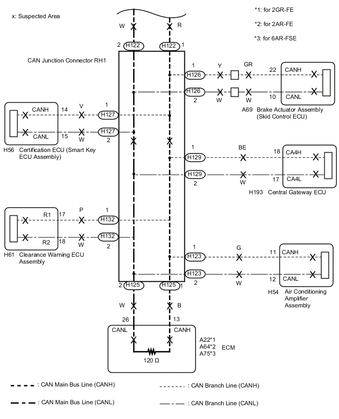
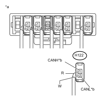
While observing the resistance value shown on the electrical tester, disconnect connectors (H123, H126, H127, H129 and H132) from the CAN junction connector RH1 one by one until the resistance becomes normal (between 54 and 69 Ω).
Tech Tips
-
Do not disconnect the branch line connector of the central gateway ECU.
-
Connectors that connect to the CAN junction connector can be distinguished by the color of their CAN bus lines.
-
Reconnecting the connectors to non-original positions on the CAN junction connector does not affect system performance. However, it is preferred to reconnect the connectors to their original positions to avoid negative effects on the wiring such as tension on the wiring harnesses, and to make future maintenance easier.
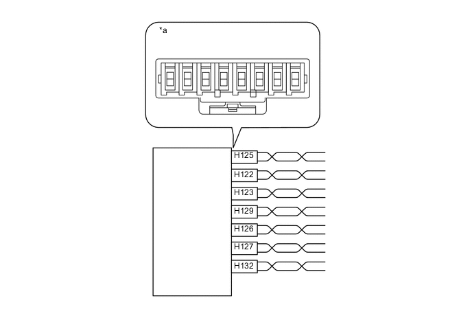
Text in Illustration *a Component without harness connected
(CAN Junction Connector RH1)
- - Wiring Color CAN Junction Connector RH1 Side Code Color (CANH Side) Color (CANL Side) ECM H125 B W CAN main bus line (bus line connecting CAN junction connector RH1 and CAN junction connector LH1) H122 R W Air conditioning amplifier assembly H123 G W Central gateway ECU H129 BE W Brake actuator assembly (skid control ECU) H126 Y W Certification ECU (smart key ECU assembly) H127 V W Clearance warning ECU assembly H132 P W Note
Do not reconnect the disconnected connectors until this inspection is complete because there may be a short in 2 or more branch lines.
Result Symptom Proceed to The resistance is still below 54 Ω when all the specified connectors are disconnected. (There are no shorts between a pair of branch lines.) A The resistance becomes normal (between 54 and 69 Ω) when a connector is disconnected. (There is a short between one or more pairs of branch lines.) B -
-
When there is a short in one or more of the branch lines:
-
Reconnect all of the connectors to the CAN junction connector, except for the one that was disconnected last (the short-circuited bus line). Check that the resistance shown on the tester is normal (between 54 and 69 Ω) to confirm that there is a short in the one branch line only.
-
B
CHECK FOR SHORT IN CAN BUS LINES (ECU, SENSOR) Click here
A
-
-
CHECK FOR SHORT IN CAN BUS LINES (CAN J/C LH1 - CAN J/C RH1)
-
Reconnect all of the connectors to the CAN junction connector RH1.
-
Text in Illustration *a Rear view of wire harness connector
(to CAN Junction Connector RH1)
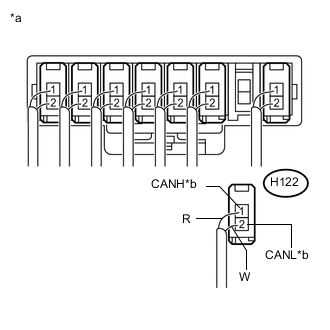
*b to CAN Junction Connector LH1 Disconnect the H122 CAN main bus line connector.
Tech Tips
-
Connectors that connect to the CAN junction connector can be distinguished by the color of their CAN bus lines.
-
Reconnecting the connectors to non-original positions on the CAN junction connector does not affect system performance. However, it is preferred to reconnect the connectors to their original positions to avoid negative effects on the wiring such as tension on the wiring harnesses, and to make future maintenance easier.
-
-
Text in Illustration *a Front view of wire harness connector
(to Central Gateway ECU)
Measure the resistance according to the value(s) in the table below.
Standard Resistance Tester Connection Condition Specified Condition H193-18 (CA4H) - H193-17 (CA4L) Cable disconnected from negative (-) battery terminal 108 to 132 Ω
OK
CHECK FOR SHORT IN CAN BUS LINES (CAN J/C LH1 - CAN J/C RH1) Click here
NG
-
-
CHECK FOR SHORT IN CAN BUS LINES (CAN J/C RH1)
-
Reconnect the H122 CAN main bus line connector.
-
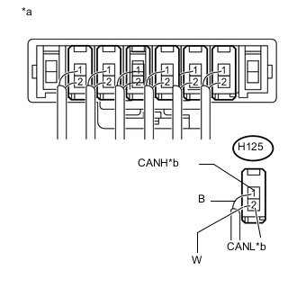
Text in Illustration *a Rear view of wire harness connector
(to CAN Junction Connector RH1)
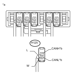
*b to ECM Disconnect the H125 ECM main bus line connector.
Tech Tips
-
Connectors that connect to the CAN junction connector can be distinguished by the color of their CAN bus lines.
-
Reconnecting the connectors to non-original positions on the CAN junction connector does not affect system performance. However, it is preferred to reconnect the connectors to their original positions to avoid negative effects on the wiring such as tension on the wiring harnesses, and to make future maintenance easier.
-
-
Text in Illustration *a Front view of wire harness connector
(to Central Gateway ECU)
Measure the resistance according to the value(s) in the table below.
Standard Resistance Tester Connection Condition Specified Condition H193-18 (CA4H) - H193-17 (CA4L) Cable disconnected from negative (-) battery terminal 108 to 132 Ω
NG
REPLACE CAN JUNCTION CONNECTOR RH1
OK
-
-
CHECK FOR SHORT IN CAN BUS LINES (ECM MAIN BUS LINE)
-
Reconnect the H125 ECM main bus line connector.
-
Disconnect the A22, A64 or A75 ECM connector.
-
Text in Illustration *a Front view of wire harness connector
(to Central Gateway ECU)
Measure the resistance according to the value(s) in the table below.
Standard Resistance Tester Connection Condition Specified Condition H193-18 (CA4H) - H193-17 (CA4L) Cable disconnected from negative (-) battery terminal 108 to 132 Ω Result Result Proceed to OK (for 2GR-FE) A OK (for 2AR-FE) B OK (for 6AR-FSE) C NG D
A
REPLACE ECM Click here
B
REPLACE ECM Click here
C
REPLACE ECM Click here
D
REPAIR OR REPLACE CAN MAIN BUS LINES (ECM MAIN LINES)
-
-
CHECK FOR SHORT IN CAN BUS LINES (COMBINATION METER ASSEMBLY MAIN BUS LINE)
-
Reconnect the H213 CAN junction connector LH1.
-
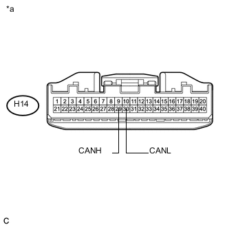
Text in Illustration *a Front view of wire harness connector
(to Combination Meter Assembly)
Disconnect the H14 combination meter assembly connector.
-
Measure the resistance according to the value(s) in the table below.
Standard Resistance Tester Connection Condition Specified Condition H14-29 (CANH) - H14-30 (CANL) Cable disconnected from negative (-) battery terminal 108 to 132 Ω
OK
REPLACE COMBINATION METER ASSEMBLY Click here
NG
REPAIR OR REPLACE CAN MAIN BUS LINES (COMBINATION METER ASSEMBLY MAIN LINES)
-
-
CHECK FOR SHORT IN CAN BUS LINES (CENTRAL GATEWAY ECU BRANCH LINE)
-
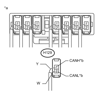
Text in Illustration *a Rear view of wire harness connector
(to CAN Junction Connector RH1)
*b to Central Gateway ECU Disconnect the H129 central gateway ECU branch line connector.
Tech Tips
-
Connectors that connect to the CAN junction connector can be distinguished by the color of their CAN bus lines.
-
Reconnecting the connectors to non-original positions on the CAN junction connector does not affect system performance. However, it is preferred to reconnect the connectors to their original positions to avoid negative effects on the wiring such as tension on the wiring harnesses, and to make future maintenance easier.
-
-
Text in Illustration *a Front view of wire harness connector
(to Central Gateway ECU)
Measure the resistance according to the value(s) in the table below.
Standard Resistance Tester Connection Condition Specified Condition H193-18 (CA4H) - H193-17 (CA4L) Cable disconnected from negative (-) battery terminal 1 MΩ or higher
NG
REPAIR OR REPLACE CAN BRANCH LINE CONNECTED TO CENTRAL GATEWAY ECU
OK
-
-
CHECK FOR SHORT IN CAN BUS LINES (BRANCH LINE)
-
Reconnect the H129 central gateway ECU branch line connector.
-
Text in Illustration *a Front view of wire harness connector
(to Central Gateway ECU)
Connect the probes of an electrical tester to terminals 18 (CA4H) and 17 (CA4L) of the H193 central gateway ECU connector.
-
While observing the resistance value shown on the electrical tester, disconnect connectors (H118, H120, H123, H126, H127, H132, H167, H211 and H214) from the CAN junction connector LH1 and CAN junction connector RH1 one by one until the resistance becomes normal (between 54 and 69 Ω).
Tech Tips
-
Do not disconnect the branch line connector of the central gateway ECU.
-
Connectors that connect to the CAN junction connector can be distinguished by the color of their CAN bus lines.
-
Reconnecting the connectors to non-original positions on the CAN junction connector does not affect system performance. However, it is preferred to reconnect the connectors to their original positions to avoid negative effects on the wiring such as tension on the wire harnesses, and to make future maintenance easier.
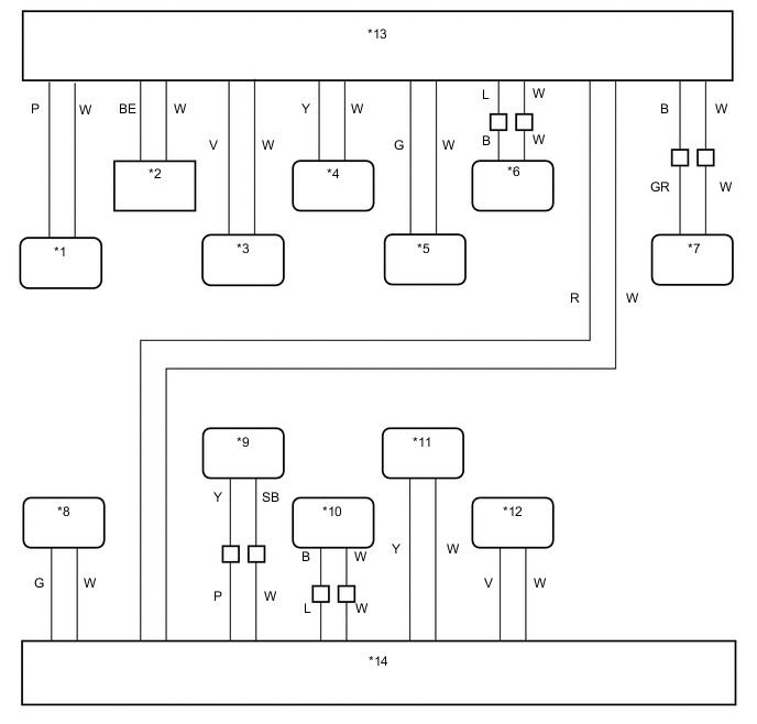
Text in Illustration *1 Clearance Warning ECU Assembly *2 Steering Sensor *3 Certification ECU (Smart Key ECU Assembly) *4 Central Gateway ECU *5 Combination Meter Assembly *6 Headlight Leveling ECU (Headlight Swivel ECU Assembly) *7 Brake Actuator Assembly (Skid Control ECU) *8 Air Conditioning Amplifier Assembly *9 Power Steering ECU with Motor Assembly *10 ECM *11 Airbag Sensor Assembly *12 Main Body ECU (Multiplex Network Body ECU) *13 CAN Junction Connector RH1 *14 CAN Junction Connector LH1 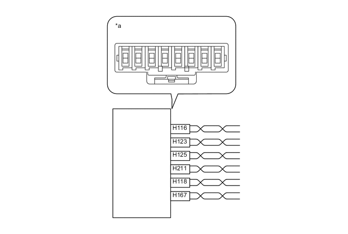
Text in Illustration *a Component without harness connected
(CAN Junction Connector LH1)
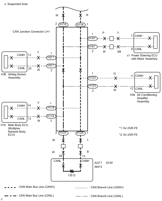
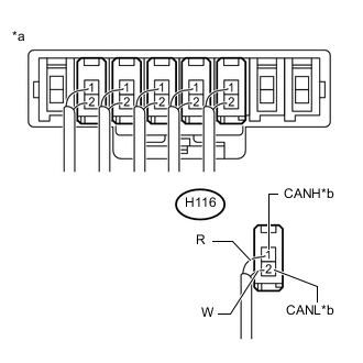
- - Wiring Color CAN Junction Connector LH1 Side Code Color (CANH Side) Color (CANL Side) CAN main bus line (bus line connecting CAN junction connector LH1 and CAN junction connector RH1) H116 R W Air conditioning amplifier assembly H123 G W ECM H125 L W Airbag sensor assembly H211 Y W Main body ECU (multiplex network body ECU) H118 V W Power steering ECU with motor assembly H167 P W 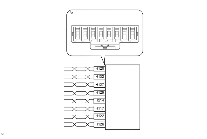
Text in Illustration *a Component without harness connected
(CAN Junction Connector RH1)
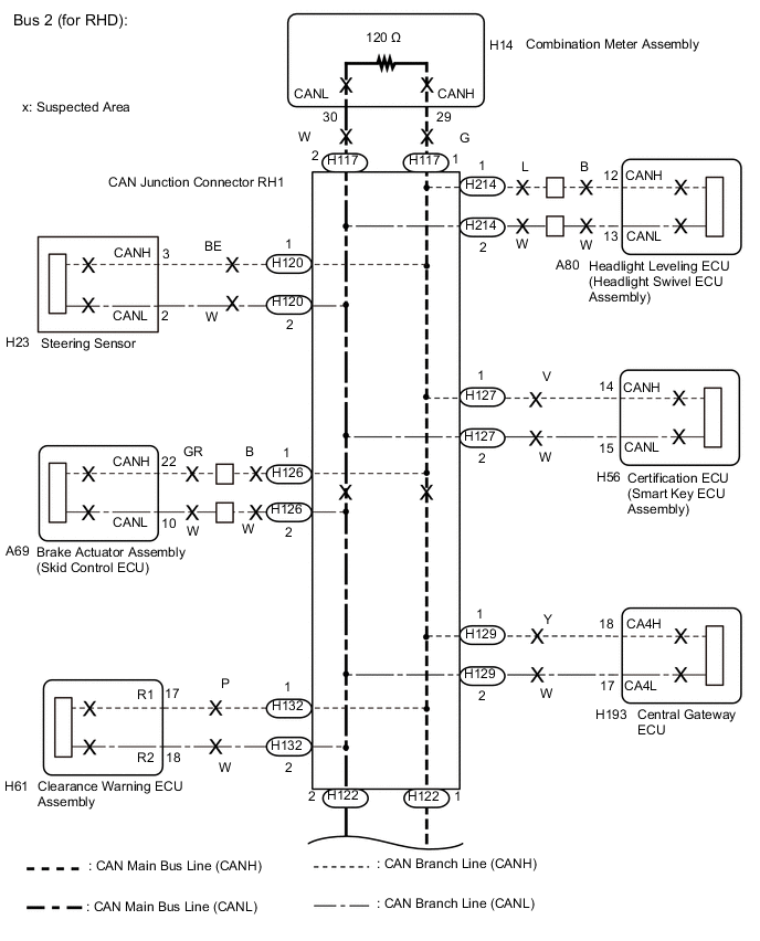
- - Wiring Color CAN Junction Connector RH1 Side Code Color (CANH Side) Color (CANL Side) Steering sensor H120 BE W Clearance warning ECU assembly H132 P W Certification ECU (smart key ECU assembly) H127 V W Central gateway ECU H129 Y W Headlight leveling ECU (headlight swivel ECU assembly) H214 L W Combination meter assembly H117 G W CAN main bus line (bus line connecting CAN junction connector LH1 and CAN junction connector RH1) H122 R W Brake actuator assembly (skid control ECU) H126 B W Note
Do not reconnect the disconnected connectors until this inspection is complete because there may be a short in 2 or more branch lines.
Result Symptom Proceed to The resistance is still below 54 Ω when all the specified connectors are disconnected. (There are no shorts between a pair of branch lines.) A The resistance becomes normal (between 54 and 69 Ω) when a connector is disconnected. (There is a short between one or more pairs of branch lines.) B -
-
When there is a short in one or more of the branch lines:
-
Reconnect all of the connectors to the CAN junction connector, except for the one that was disconnected last (the short-circuited bus line). Check that the resistance shown on the electrical tester is normal (between 54 and 69 Ω) to confirm that there is a short in the one branch line only.
-
B
CHECK FOR SHORT IN CAN BUS LINES (ECU, SENSOR) Click here
A
-
-
CHECK FOR SHORT IN CAN BUS LINES (COMBINATION METER ASSEMBLY MAIN BUS LINE)
-
Reconnect all of the connectors to the CAN junction connector LH1 and CAN junction connector RH1.
-
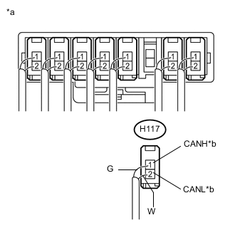
Text in Illustration *a Rear view of wire harness connector
(to CAN Junction Connector RH1)
*b to Combination Meter Assembly Disconnect the H117 combination meter assembly main bus line connector.
Tech Tips
-
Connectors that connect to the CAN junction connector can be distinguished by the color of their CAN bus lines.
-
Reconnecting the connectors to non-original positions on the CAN junction connector does not affect system performance. However, it is preferred to reconnect the connectors to their original positions to avoid negative effects on the wiring such as tension on the wiring harnesses, and to make future maintenance easier.
-
-
Text in Illustration *a Front view of wire harness connector
(to Central Gateway ECU)
Measure the resistance according to the value(s) in the table below.
Standard Resistance Tester Connection Condition Specified Condition H193-18 (CA4H) - H193-17 (CA4L) Cable disconnected from negative (-) battery terminal 108 to 132 Ω
NG
CHECK FOR SHORT IN CAN BUS LINES (ECM MAIN BUS LINE) Click here
OK
-
-
CHECK FOR SHORT IN CAN BUS LINES (COMBINATION METER ASSEMBLY)
-
Reconnect the H117 combination meter assembly main bus line connector.
-
Disconnect the H14 combination meter assembly connector.
-
Text in Illustration *a Front view of wire harness connector
(to Central Gateway ECU)
Measure the resistance according to the value(s) in the table below.
Standard Resistance Tester Connection Condition Specified Condition H193-18 (CA4H) - H193-17 (CA4L) Cable disconnected from negative (-) battery terminal 108 to 132 Ω Tech Tips
If the resistance becomes normal (between 108 to 132 Ω) when the connector is disconnected, there may be a short in the combination meter assembly.
OK
REPLACE COMBINATION METER ASSEMBLY Click here
NG
REPAIR OR REPLACE CAN MAIN BUS LINES (COMBINATION METER ASSEMBLY MAIN LINES)
-
-
CHECK FOR SHORT IN CAN BUS LINES (ECM MAIN BUS LINE)
-
Reconnect the H117 combination meter assembly main bus line connector.
-
Text in Illustration *a Rear view of wire harness connector
(to CAN Junction Connector LH1)
*b to ECM Disconnect the H125 ECM main bus line connector.
Tech Tips
-
Connectors that connect to the CAN junction connector can be distinguished by the color of their CAN bus lines.
-
Reconnecting the connectors to non-original positions on the CAN junction connector does not affect system performance. However, it is preferred to reconnect the connectors to their original positions to avoid negative effects on the wiring such as tension on the wiring harnesses, and to make future maintenance easier.
-
-
Text in Illustration *a Front view of wire harness connector
(to Central Gateway ECU)
Measure the resistance according to the value(s) in the table below.
Standard Resistance Tester Connection Condition Specified Condition H193-18 (CA4H) - H193-17 (CA4L) Cable disconnected from negative (-) battery terminal 108 to 132 Ω
NG
CHECK FOR SHORT IN CAN BUS LINES (CAN J/C RH1) Click here
OK
-
-
CHECK FOR SHORT IN CAN BUS LINES (ECM)
-
Reconnect the H125 ECM main bus line connector.
-
Disconnect the A22 or A64 ECM connector.
-
Text in Illustration *a Front view of wire harness connector
(to Central Gateway ECU)
Measure the resistance according to the value(s) in the table below.
Standard Resistance Tester Connection Condition Specified Condition H193-18 (CA4H) - H193-17 (CA4L) Cable disconnected from negative (-) battery terminal 108 to 132 Ω Result Result Proceed to OK (for 2GR-FE) A OK (for 2AR-FE) B NG C
A
REPLACE ECM Click here
B
REPLACE ECM Click here
C
REPAIR OR REPLACE CAN MAIN BUS LINES (ECM MAIN LINES)
-
-
CHECK FOR SHORT IN CAN BUS LINES (CAN J/C RH1)
-
Reconnect the H125 ECM main bus line connector.
-
Text in Illustration *a Rear view of wire harness connector
(to CAN Junction Connector RH1)
*b to CAN Junction Connector LH1 Disconnect the H122 CAN main bus line connector.
Tech Tips
-
Connectors that connect to the CAN junction connector can be distinguished by the color of their CAN bus lines.
-
Reconnecting the connectors to non-original positions on the CAN junction connector does not affect system performance. However, it is preferred to reconnect the connectors to their original positions to avoid negative effects on the wiring such as tension on the wiring harnesses, and to make future maintenance easier.
-
-
Text in Illustration *a Front view of wire harness connector
(to Central Gateway ECU)
Measure the resistance according to the value(s) in the table below.
Standard Resistance Tester Connection Condition Specified Condition H193-18 (CA4H) - H193-17 (CA4L) Cable disconnected from negative (-) battery terminal 108 to 132 Ω
NG
REPLACE CAN JUNCTION CONNECTOR RH1
OK
-
-
CHECK FOR SHORT IN CAN BUS LINES (CAN J/C LH1 - CAN J/C RH1)
-
Reconnect the H122 CAN main bus line connector.
-
Text in Illustration *a Rear view of wire harness connector
(to CAN Junction Connector LH1)
*b to CAN Junction Connector RH1 Disconnect the H116 CAN main bus line connector.
Tech Tips
-
Connectors that connect to the CAN junction connector can be distinguished by the color of their CAN bus lines.
-
Reconnecting the connectors to non-original positions on the CAN junction connector does not affect system performance. However, it is preferred to reconnect the connectors to their original positions to avoid negative effects on the wiring such as tension on the wiring harnesses, and to make future maintenance easier.
-
-
Text in Illustration *a Front view of wire harness connector
(to Central Gateway ECU)
Measure the resistance according to the value(s) in the table below.
Standard Resistance Tester Connection Condition Specified Condition H193-18 (CA4H) - H193-17 (CA4L) Cable disconnected from negative (-) battery terminal 108 to 132 Ω
OK
REPLACE CAN JUNCTION CONNECTOR LH1
NG
REPAIR OR REPLACE CAN MAIN BUS LINES (CAN J/C LH1 - CAN J/C RH1)
-
-
CHECK FOR SHORT IN CAN BUS LINES (ECU, SENSOR)
-
Reconnect all of the connectors to the CAN junction connector LH1 and CAN junction connector RH1.
-
Disconnect the connector that includes terminals CANH and CANL from the ECU or sensor to which the short circuited branch line is connected Click here.
-
Measure the resistance according to the value(s) in the table below.
Standard Resistance Tester Connection Condition Specified Condition H193-18 (CA4H) - H193-17 (CA4L) Cable disconnected from negative (-) battery terminal 54 to 69 Ω Text in Illustration *a Front view of wire harness connector
(to Central Gateway ECU)
Tech Tips
If the resistance becomes normal (between 54 and 69 Ω) when the connector is disconnected from the ECU or sensor, there may be a short in the ECU or sensor.
OK
REPLACE CORRESPONDING ECU OR SENSOR
NG
REPAIR OR REPLACE CORRESPONDING ECU OR SENSOR BRANCH LINES OR CONNECTOR
-