CAN COMMUNICATION SYSTEM(w/ Central Gateway ECU) Open in Bus 2 Main Bus Line
DESCRIPTION
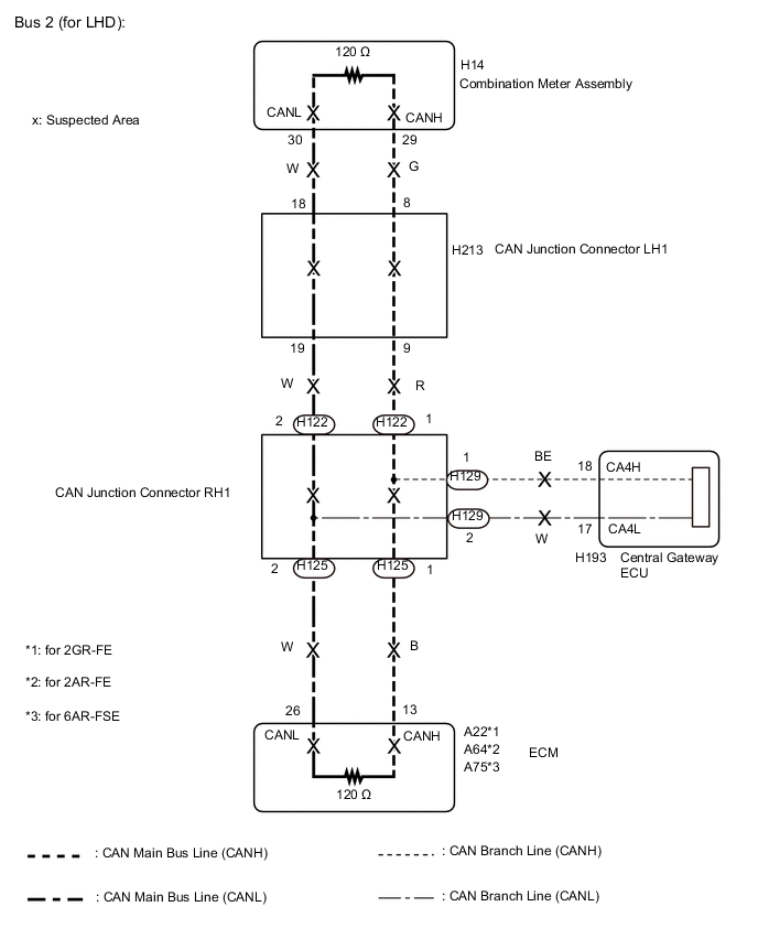
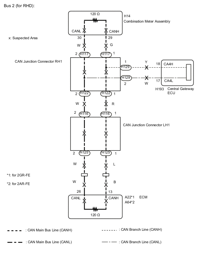
There may be an open circuit in one of the bus 2 main lines and/or a central gateway ECU branch line when the resistance between terminals 18 (CA4H) and 17 (CA4L) of the central gateway ECU is 70 Ω or higher.
| Symptom | Trouble Area |
|---|---|
| Resistance between terminals 18 (CA4H) and 17 (CA4L) of central gateway ECU is 70 Ω or higher. |
|
This malfunction is not related to the lines of a bus 2 branch except the central gateway ECU branch lines or to ECUs or sensors connected to a bus 2 branch.
WIRING DIAGRAM
CAUTION / NOTICE / HINT
Note
-
Before measuring the resistance of the CAN bus, turn the engine switch off and leave the vehicle for 1 minute or more without operating the key or any switches, or opening or closing the doors. After that, disconnect the cable from the negative (-) battery terminal and leave the vehicle for 1 minute or more before measuring the resistance.
-
After turning the engine switch off, waiting time may be required before disconnecting the cable from the negative (-) battery terminal. Therefore, make sure to read the disconnecting the cable from the negative (-) battery terminal notices before proceeding with work Click here.
-
Because the order of diagnosis is important to allow correct diagnosis, make sure to begin troubleshooting using How to Proceed with Troubleshooting when CAN communication system related DTCs are output Click here.
-
After performing repairs, perform the DTC check procedure and confirm that the DTCs are not output again.
-
DTC check procedure: Drive the vehicle at a speed of 36 km/h (22 mph) or more for 5 minutes or more.
-
After the repair, perform the CAN bus check and check that all the ECUs and sensors connected to the CAN communication system are displayed Click here.
Tech Tips
-
Operating the engine switch, any other switches or a door triggers related ECU and sensor communication on the CAN. This communication will cause the resistance value to change.
-
Even after DTCs are cleared, if a DTC is stored again after driving the vehicle for a while, the malfunction may be occurring due to vibration of the vehicle. In such a case, wiggling the ECUs or wire harness while performing the inspection below may help determine the cause of the malfunction.
-
Connectors that connect to the CAN junction connector can be distinguished by the color of their CAN bus lines. When the connectors have been disconnected from the CAN junction connector, reconnecting the connectors to non-original positions on the CAN junction connector does not affect system performance. However, it is preferred to reconnect the connectors to their original positions to avoid negative effects on the wiring such as tension on the wiring harnesses, and to make future maintenance easier.
PROCEDURE
-
CHECK FOR OPEN IN CAN BUS LINES (CENTRAL GATEWAY ECU BRANCH LINE)
-
Disconnect the cable from the negative (-) battery terminal.
-
Measure the resistance according to the value(s) in the table below.
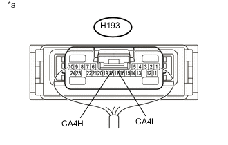
Standard Resistance Tester Connection Condition Specified Condition H193-18 (CA4H) - H193-17 (CA4L) Cable disconnected from negative (-) battery terminal 108 to 132 Ω Text in Illustration *a Component with harness connected
(Central Gateway ECU)
Note
When the measured value is 133 Ω or higher and a CAN communication system DTC is output, there may be a fault besides disconnection of the central gateway ECU branch line. For that reason, troubleshooting should be performed again from How to Proceed with Troubleshooting after repairing the trouble area Click here.
NG 
REPAIR OR REPLACE CAN BRANCH LINE CONNECTED TO CENTRAL GATEWAY ECU
OK 
-
-
CHECK FOR OPEN IN CAN BUS LINES (ECM)
-
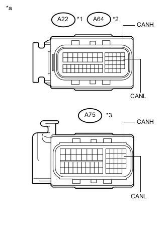
Text in Illustration *1 for 2GR-FE *2 for 2AR-FE *3 for 6AR-FSE *a Front view of wire harness connector
(to ECM)
Disconnect the A22, A64 or A75 ECM connector.
-
Measure the resistance according to the value(s) in the table below.
Standard Resistance (for 2GR-FE) Tester Connection Condition Specified Condition A22-13 (CANH) -A22-26 (CANL) Cable disconnected from negative (-) battery terminal 108 to 132 Ω Standard Resistance (for 2AR-FE) Tester Connection Condition Specified Condition A64-13 (CANH) -A64-26 (CANL) Cable disconnected from negative (-) battery terminal 108 to 132 Ω Standard Resistance (for 6AR-FSE) Tester Connection Condition Specified Condition A75-13 (CANH) -A75-26 (CANL) Cable disconnected from negative (-) battery terminal 108 to 132 Ω Result Result Proceed to OK (for 2GR-FE) A OK (for 2AR-FE) B OK (for 6AR-FSE) C NG D
A
REPLACE ECM Click here
B
REPLACE ECM Click here
C
REPLACE ECM Click here
D
-
-
CHECK FOR OPEN IN CAN BUS LINES (COMBINATION METER ASSEMBLY)
-
Reconnect the A22, A64 or A75 ECM connector.
-
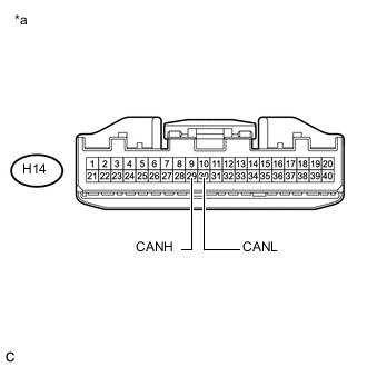
Text in Illustration *a Front view of wire harness connector
(to Combination Meter Assembly)
Disconnect the H14 combination meter assembly connector.
-
Measure the resistance according to the value(s) in the table below.
Standard Resistance Tester Connection Condition Specified Condition H14-29 (CANH) - H14-30 (CANL) Cable disconnected from negative (-) battery terminal 108 to 132 Ω Result Result Proceed to OK A NG (for LHD) B NG (for RHD) C
A
REPLACE COMBINATION METER ASSEMBLY Click here
C 
CHECK FOR OPEN IN CAN BUS LINES (CAN J/C RH1) Click here
B
-
-
CHECK FOR OPEN IN CAN BUS LINES (CAN J/C RH1)
-
Reconnect the H14 combination meter assembly connector.
-
Disconnect the H122 and H125 CAN junction connector RH1.
Tech Tips
-
Connectors that connect to the CAN junction connector can be distinguished by the color of their CAN bus lines.
-
Reconnecting the connectors to non-original positions on the CAN junction connector does not affect system performance. However, it is preferred to reconnect the connectors to their original positions to avoid negative effects on the wiring such as tension on the wiring harnesses, and to make future maintenance easier.
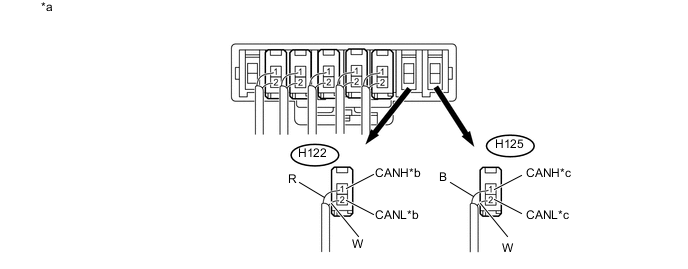
Text in Illustration *a Rear view of wire harness connector
(to CAN Junction Connector RH1)
*b to CAN Junction Connector LH1 *c to ECM - - Wiring Color Code Color (CANH Side) Color (CANL Side) Connected to H122 R W CAN junction connector LH1 H125 B W ECM -
-
Measure the resistance according to the value(s) in the table below.
Standard Resistance Tester Connection Condition Specified Condition Connected to H122-1 (CANH) - H122-2 (CANL) Cable disconnected from negative (-) battery terminal 108 to 132 Ω CAN junction connector LH1 H125-1 (CANH) - H125-2 (CANL) Cable disconnected from negative (-) battery terminal 108 to 132 Ω ECM Result Result Proceed to OK A NG (CAN junction connector LH1 main line) B NG (ECM main line) C
A
REPLACE CAN JUNCTION CONNECTOR RH1
C
REPAIR OR REPLACE CAN MAIN BUS LINE OR CONNECTOR (ECM MAIN LINE)
B
-
-
CHECK FOR OPEN IN CAN BUS LINES (CAN J/C LH1)
-
Reconnect the H122 and H125 CAN junction connector RH1.
-
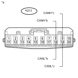
Text in Illustration *a Front view of wire harness connector
(to CAN junction Connector LH1)
*b to Combination Meter Assembly *c to CAN Junction Connector RH1 Disconnect the H213 CAN junction connector LH1.
-
Measure the resistance according to the value(s) in the table below.
Standard Resistance Tester Connection Condition Specified Condition Connected to H213-8 (CANH) - H213-18 (CANL) Cable disconnected from negative (-) battery terminal 108 to 132 Ω Combination meter assembly H213-9 (CANH) - H213-19 (CANL) Cable disconnected from negative (-) battery terminal 108 to 132 Ω CAN junction connector RH1 Result Result Proceed to OK A NG (Combination meter assembly main line) B NG (CAN junction connector RH1) C
A
REPLACE CAN JUNCTION CONNECTOR LH1
B
REPAIR OR REPLACE CAN MAIN BUS LINE OR CONNECTOR (COMBINATION METER ASSEMBLY MAIN LINE)
C
REPAIR OR REPLACE CAN MAIN BUS LINE OR CONNECTOR (CAN J/C LH1 - CAN J/C RH1)
-
-
CHECK FOR OPEN IN CAN BUS LINES (CAN J/C RH1)
-
Reconnect the H14 combination meter assembly connector.
-
Disconnect the H117 and H122 CAN junction connector RH1.
Tech Tips
-
Connectors that connect to the CAN junction connector can be distinguished by the color of their CAN bus lines.
-
Reconnecting the connectors to non-original positions on the CAN junction connector does not affect system performance. However, it is preferred to reconnect the connectors to their original positions to avoid negative effects on the wiring such as tension on the wiring harnesses, and to make future maintenance easier.
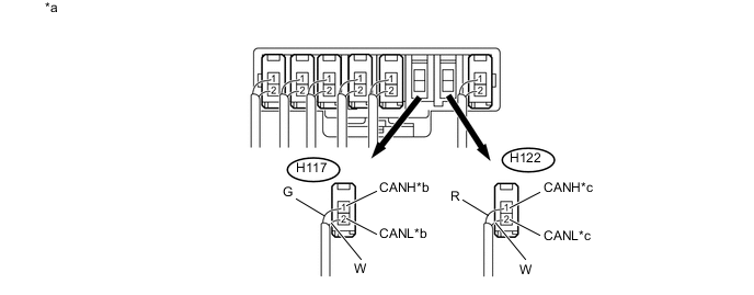
Text in Illustration *a Rear view of wire harness connector
(to CAN junction Connector RH1)
*b to Combination Meter Assembly *c to CAN Junction Connector LH1 - - Wiring Color Code Color (CANH Side) Color (CANL Side) Connected to H117 G W Combination meter assembly H122 R W CAN junction connector LH1 -
-
Measure the resistance according to the value(s) in the table below.
Standard Resistance Tester Connection Condition Specified Condition Connected to H117-1 (CANH) - H117-2 (CANL) Cable disconnected from negative (-) battery terminal 108 to 132 Ω Combination meter assembly H122-1 (CANH) - H122-2 (CANL) Cable disconnected from negative (-) battery terminal 108 to 132 Ω CAN junction connector LH1 Result Result Proceed to OK A NG (CAN junction connector LH1) B NG (Combination meter assembly main line) C
A
REPLACE CAN JUNCTION CONNECTOR RH1
C
REPAIR OR REPLACE CAN MAIN BUS LINE OR CONNECTOR (COMBINATION METER ASSEMBLY MAIN LINE)
B
-
-
CHECK FOR OPEN IN CAN BUS LINES (CAN J/C LH1)
-
Reconnect the H117 and H122 CAN junction connector RH1.
-
Disconnect the H116 and H125 CAN junction connector LH1.
Tech Tips
-
Connectors that connect to the CAN junction connector can be distinguished by the color of their CAN bus lines.
-
Reconnecting the connectors to non-original positions on the CAN junction connector does not affect system performance. However, it is preferred to reconnect the connectors to their original positions to avoid negative effects on the wiring such as tension on the wiring harnesses, and to make future maintenance easier.
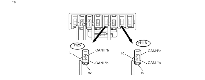
Text in Illustration *a Rear view of wire harness connector
(to CAN junction Connector LH1)
*b to ECM *c to CAN junction Connector RH1 - - Wiring Color Code Color (CANH Side) Color (CANL Side) Connected to H125 L W ECM H116 R W CAN junction connector RH1 -
-
Measure the resistance according to the value(s) in the table below.
Standard Resistance Tester Connection Condition Specified Condition Connected to H125-1 (CANH) - H125-2 (CANL) Cable disconnected from negative (-) battery terminal 108 to 132 Ω ECM H116-1 (CANH) - H116-2 (CANL) Cable disconnected from negative (-) battery terminal 108 to 132 Ω CAN junction connector RH1 Result Result Proceed to OK A NG (ECM main line) B NG (CAN junction connector RH1 main line) C
A
REPLACE CAN JUNCTION CONNECTOR LH1
B
REPAIR OR REPLACE CAN MAIN BUS LINE OR CONNECTOR (ECM MAIN LINE)
C
REPAIR OR REPLACE CAN MAIN BUS LINE OR CONNECTOR (CAN J/C LH1 - CAN J/C RH1)
-