CAN COMMUNICATION SYSTEM(w/ Central Gateway ECU), Diagnostic DTC:U1002
| DTC Code | DTC Name |
|---|---|
| U1002 | Lost Communication with Gateway Module (Main Body ECU) |
DESCRIPTION
-
The main body ECU (multiplex network body ECU) will store this DTC when no signals can be received from the ECUs that have been memorized as those that are connected to sub bus 1.
-
When the main body ECU (multiplex network body ECU) receives a response signal from the ECUs connected to sub bus 1, the main body ECU (multiplex network body ECU) recognizes and memorizes that the ECU is connected to sub bus 1. Based on this memorized data, the main body ECU (multiplex network body ECU) monitors for malfunctions in the ECUs connected to sub bus 1 when communicating with those ECUs. If the main body ECU (multiplex network body ECU) cannot receive response signals from the ECUs that have been memorized as those connected to sub bus 1, the main body ECU (multiplex network body ECU) determines that a malfunction exists.
| DTC No. | DTC Detection Condition | Trouble Area |
|---|---|---|
| U1002 | The main body ECU (multiplex network body ECU) cannot receive signals from all ECUs that have been memorized as those connected to sub bus 1. |
|
-
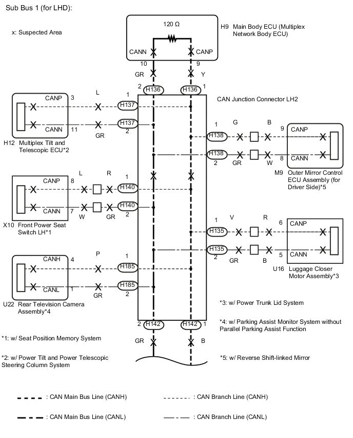
*1: w/ Seat Position Memory System
-
*2: w/ Reverse Shift-linked Mirror
-
*3: w/ Power Tilt and Power Telescopic Steering Column System
-
*4: w/ Power Trunk Lid System
-
*5: w/ Parking Assist Monitor System without Parallel Parking Assist Function
Tech Tips
This diagnosis procedure is for when DTC U1002 is output by the main body ECU (multiplex network body ECU) (GTS display: Main Body).
WIRING DIAGRAM
CAUTION / NOTICE / HINT
Note
-
Before measuring the resistance of the CAN bus, turn the engine switch off and leave the vehicle for 1 minute or more without operating the key or any switches, or opening or closing the doors. After that, disconnect the cable from the negative (-) battery terminal and leave the vehicle for 1 minute or more before measuring the resistance.
-
After turning the engine switch off, waiting time may be required before disconnecting the cable from the negative (-) battery terminal. Therefore, make sure to read the disconnecting the cable from the negative (-) battery terminal notices before proceeding with work Click here.
-
Because the order of diagnosis is important to allow correct diagnosis, make sure to begin troubleshooting using How to Proceed with Troubleshooting when CAN communication system related DTCs are output Click here.
-
After performing repairs, perform the DTC check procedure and confirm that the DTCs are not output again.
-
DTC check procedure: Turn the engine switch on (IG) and wait at least 20 seconds.
-
After the repair, perform CAN bus check and check that all the ECUs and sensors connected to the CAN communication system are displayed Click here.
-
If the main body ECU (multiplex network body ECU) is replaced, refer to Service Bulletin.
Tech Tips
-
Operating the engine switch, any other switches or a door triggers related ECU and sensor communication on the CAN. This communication will cause the resistance value to change.
-
Even after DTCs are cleared, if a DTC is stored again after driving the vehicle for a while, the malfunction may be occurring due to vibration of the vehicle. In such a case, wiggling the ECUs or wire harness while performing the inspection below may help determine the cause of the malfunction.
-
Connectors that connect to the CAN junction connector can be distinguished by the color of their CAN bus lines. When the connectors have been disconnected from the CAN junction connector, reconnecting the connectors to non-original positions on the CAN junction connector does not affect system performance. However, it is preferred to reconnect the connectors to their original positions to avoid negative effects on the wiring such as tension on the wire harnesses, and to make future maintenance easier.
PROCEDURE
-
CHECK VEHICLE TYPE
-
Check vehicle type.
Result Result Proceed to for LHD A for RHD B
B 
CHECK SUB BUS 1 Click here
A 
-
-
CHECK SUB BUS 1
-
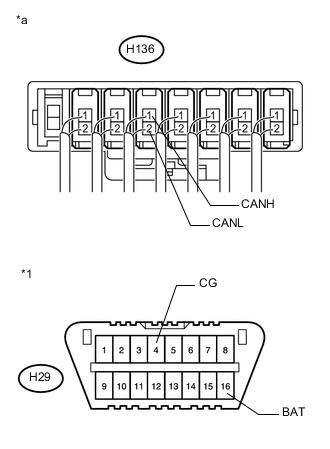
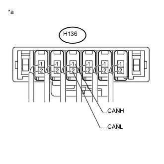
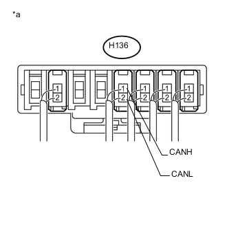
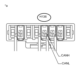
Text in Illustration *1 DLC3 *a Component with harness connected
(CAN Junction Connector LH2)
Disconnect the cable from the negative (-) battery terminal.
-
Measure the resistance according to the value(s) in the table below.
Standard Resistance Tester Connection Condition Specified Condition Result H136-1 (CANH) - H136-2 (CANL) Cable disconnected from negative (-) battery terminal 54 to 69 Ω Below 54 Ω:
Short circuit between bus lines
70 Ω or higher:
Open circuit in a main bus line
H136-1 (CANH) - H29-4 (CG) Cable disconnected from negative (-) battery terminal 200 Ω or higher Below 200 Ω:
CANH ground short
H136-2 (CANL) - H29-4 (CG) Cable disconnected from negative (-) battery terminal 200 Ω or higher Below 200 Ω:
CANL ground short
H136-1 (CANH) - H29-16 (BAT) Cable disconnected from negative (-) battery terminal 6 kΩ or higher Below 6 kΩ:
CANH +B short
H136-2 (CANL) - H29-16 (BAT) Cable disconnected from negative (-) battery terminal 6 kΩ or higher Below 6 kΩ:
CANL +B short
Result Result Proceed to OK A Open circuit in CAN main bus line B Short circuit between bus lines C
-
Ground short
-
+B short
D -
B
CHECK FOR OPEN IN SUB BUS 1 LINES (CAN J/C LH2 - MAIN BODY ECU (MULTIPLEX NETWORK BODY ECU)) Click here
C
CHECK FOR SHORT IN SUB BUS 1 LINES (CAN J/C LH2 - MAIN BODY ECU (MULTIPLEX NETWORK BODY ECU)) Click here
D
CHECK FOR SHORT IN SUB BUS 1 LINE (CAN J/C LH2 - MAIN BODY ECU (MULTIPLEX NETWORK BODY ECU)) Click here
A
-
-
RECONFIRM DTC OUTPUT
-
Reconnect the cable to the negative (-) battery terminal.
-
Connect the GTS to the DLC3.
-
Turn the engine switch on (IG).
-
Turn the GTS on.
-
Clear the DTCs.
-
Turn the engine switch off.
-
Turn the engine switch on (IG) and recheck for DTCs.
Result Result Proceed to U1002 is output from main body ECU (multiplex network body ECU)
(GTS display: Main Body)
A Other DTC is output B
A 
REPLACE MAIN BODY ECU (MULTIPLEX NETWORK BODY ECU) Click here
B
GO TO DIAGNOSIS PROCEDURE INDICATED BY OUTPUT DTC Click here
-
-
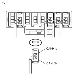
CHECK FOR OPEN IN SUB BUS 1 LINES (CAN J/C LH2 - MAIN BODY ECU (MULTIPLEX NETWORK BODY ECU))
-
Disconnect the H136 wire harness connector.
-
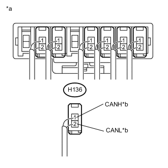
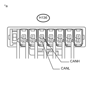
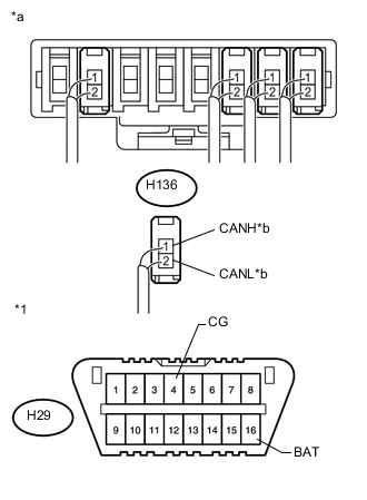
Text in Illustration *a Rear view of wire harness connector
(to CAN Junction Connector LH2)
*b to Main Body ECU (Multiplex Network Body ECU) Measure the resistance according to the value(s) in the table below.
Standard Resistance Tester Connection Condition Specified Condition H136-1 (CANH) - H136-2 (CANL) Cable disconnected from negative (-) battery terminal 108 to 132 Ω Note
-
Before disconnecting the connector, make a note of where it is connected.
-
Reconnect the connector to its original position.
-
NG
CHECK FOR OPEN IN SUB BUS 1 MAIN LINES (MAIN BODY ECU (MULTIPLEX NETWORK BODY ECU)) Click here
OK
-
-
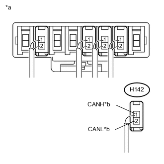
CHECK FOR OPEN IN SUB BUS 1 LINES (CAN J/C LH2)
-
Reconnect the H136 wire harness connector.
-
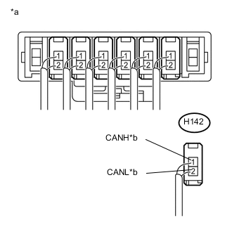
Text in Illustration *a Rear view of wire harness connector
(to CAN Junction Connector LH2)
*b to CAN Junction Connector RH2 Disconnect the H142 wire harness connector.
-
Measure the resistance according to the value(s) in the table below.
Standard Resistance Tester Connection Condition Specified Condition H142-1 (CANH) - H142-2 (CANL) Cable disconnected from negative (-) battery terminal 108 to 132 Ω Note
-
Before disconnecting the connector, make a note of where it is connected.
-
Reconnect the connector to its original position.
-
OK
REPLACE CAN JUNCTION CONNECTOR LH2
NG
-
-
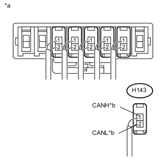
CHECK FOR OPEN IN SUB BUS 1 LINES (CAN J/C LH2 - CAN J/C RH2)
-
Reconnect the H142 wire harness connector.
-
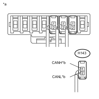
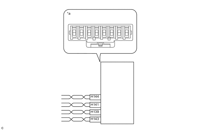
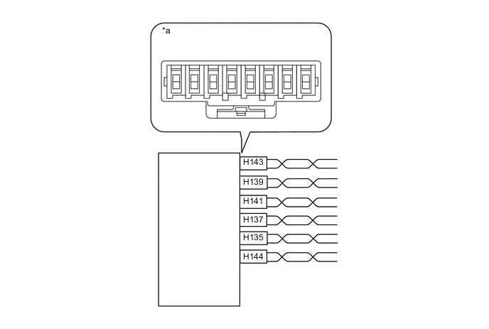
Text in Illustration *a Rear view of wire harness connector
(to CAN Junction Connector RH2)
*b to CAN Junction Connector LH2 Disconnect the H143 wire harness connector.
-
Measure the resistance according to the value(s) in the table below.
Standard Resistance Tester Connection Condition Specified Condition H143-1 (CANH) - H143-2 (CANL) Cable disconnected from negative (-) battery terminal 108 to 132 Ω Note
-
Before disconnecting the connector, make a note of where it is connected.
-
Reconnect the connector to its original position.
-
NG
REPAIR OR REPLACE CAN MAIN BUS LINE OR CONNECTOR (CAN J/C LH2 - CAN J/C RH2)
OK
-
-
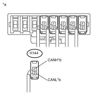
CHECK FOR OPEN IN SUB BUS 1 MAIN LINES (CAN J/C RH2)
-
Reconnect the H143 wire harness connector.
-
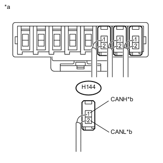
Text in Illustration *a Rear view of wire harness connector
(to CAN Junction Connector RH2)
*b to No. 1 CAN Junction Terminal Disconnect the H144 wire harness connector.
-
Measure the resistance according to the value(s) in the table below.
Standard Resistance Tester Connection Condition Specified Condition H144-1 (CANH) - H144-2 (CANL) Cable disconnected from negative (-) battery terminal 108 to 132 Ω Note
-
Before disconnecting the connector, make a note of where it is connected.
-
Reconnect the connector to its original position.
-
OK
REPLACE CAN JUNCTION CONNECTOR RH2
NG
-
-
CHECK FOR OPEN IN SUB BUS 1 MAIN LINES (NO. 1 CAN JUNCTION TERMINAL)
-
Reconnect the H144 wire harness connector.
-
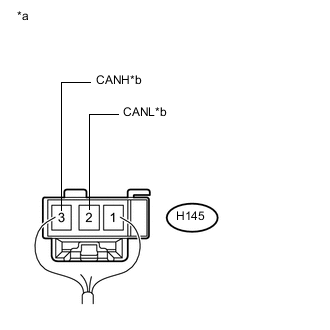
Text in Illustration *a Rear view of wire harness connector
(to No. 1 CAN Junction Terminal)
*b to CAN Junction Connector RH2 Disconnect the H145 No. 1 CAN junction terminal.
-
Measure the resistance according to the value(s) in the table below.
Standard Resistance Tester Connection Condition Specified Condition H145-3 (CANH) - H145-2 (CANL) Cable disconnected from negative (-) battery terminal 108 to 132 Ω
OK
REPLACE NO. 1 CAN JUNCTION TERMINAL
NG
REPAIR OR REPLACE CAN MAIN BUS LINE OR CONNECTOR (CAN J/C RH2 - NO. 1 CAN JUNCTION TERMINAL)
-
-
CHECK FOR OPEN IN SUB BUS 1 MAIN LINES (MAIN BODY ECU (MULTIPLEX NETWORK BODY ECU))
-
Reconnect the H136 wire harness connector.
-
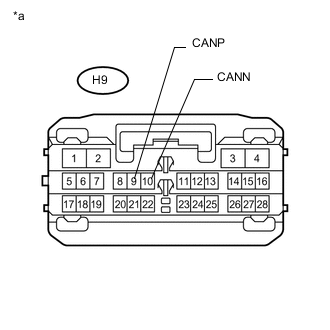
Text in Illustration *a Front view of wire harness connector
(to Main Body ECU (Multiplex Network Body ECU))
Disconnect the H9 main body ECU (multiplex network body ECU) connector.
-
Measure the resistance according to the value(s) in the table below.
Standard Resistance Tester Connection Condition Specified Condition H9-9 (CANP) - H9-10 (CANN) Cable disconnected from negative (-) battery terminal 108 to 132 Ω
OK
REPLACE MAIN BODY ECU (MULTIPLEX NETWORK BODY ECU) Click here
NG
REPAIR OR REPLACE CAN MAIN BUS LINE OR CONNECTOR (CAN J/C LH2 - MAIN BODY ECU (MULTIPLEX NETWORK BODY ECU))
-
-
CHECK FOR SHORT IN SUB BUS 1 LINES (CAN J/C LH2 - MAIN BODY ECU (MULTIPLEX NETWORK BODY ECU))
-
Disconnect the H136 wire harness connector.
-
Text in Illustration *a Rear view of wire harness connector
(to CAN Junction Connector LH2)
*b to Main Body ECU (Multiplex Network Body ECU) Measure the resistance according to the value(s) in the table below.
Standard Resistance Tester Connection Condition Specified Condition H136-1 (CANH) - H136-2 (CANL) Cable disconnected from negative (-) battery terminal 108 to 132 Ω Note
-
Before disconnecting the connector, make a note of where it is connected.
-
Reconnect the connector to its original position.
-
NG
CHECK FOR SHORT IN SUB BUS 1 LINES (MAIN BODY ECU (MULTIPLEX NETWORK BODY ECU)) Click here
OK
-
-
CHECK FOR SHORT IN SUB BUS 1 LINES (BRANCH LINE)
-
Reconnect the H136 wire harness connector.
-
Text in Illustration *a Component with harness connected
(CAN Junction Connector LH2)
Connect the probes of an ohmmeter to terminals 1 (CANH) and 2 (CANL) of the main body ECU (multiplex network body ECU) main line harness connector.
-
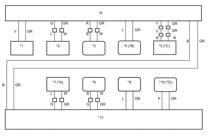
While observing the resistance value shown on the tester, disconnect connectors (H135, H137, H138, H139, H140, H141 and H185) from the CAN junction connector LH2 or CAN junction connector RH2 one by one until the resistance becomes normal (between 54 and 69 Ω).
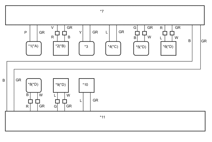
Text in Illustration *A w/ Parking Assist Monitor System without Parallel Parking Assist Function *B w/ Power Trunk Lid System *C w/ Power Tilt and Power Telescopic Steering Column System *D w/ Seat Position Memory System *1 Rear Television Camera Assembly *2 Luggage Closer Motor Assembly *3 Main Body ECU (Multiplex Network Body ECU) *4 Multiplex Tilt and Telescopic ECU *5 Outer Mirror Control ECU Assembly (for Driver Side)
(w/ Reverse Shift-linked Mirror)
*6 Front Power Seat Switch LH *7 CAN Junction Connector LH2 *8 Outer Mirror Control ECU Assembly (for Front Passenger Side)
(w/ Reverse Shift-linked Mirror)
*9 Front Power Seat Switch RH *10 No. 1 CAN Junction Terminal *11 CAN Junction Connector RH2 - - 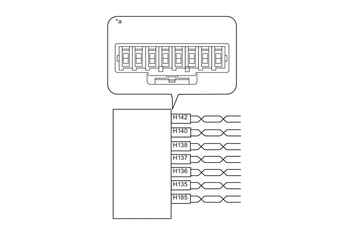
Text in Illustration *a Component without harness connected
(CAN Junction Connector LH2)
- - Wiring Color CAN Junction Connector LH2 Side Code Color (CANH Side) Color (CANL Side) Rear television camera assembly*1 H185 P GR Luggage closer motor assembly*2 H135 V GR Main body ECU (multiplex network body ECU) H136 Y GR Multiplex tilt and telescopic ECU*3 H137 L GR Outer mirror control ECU assembly (for driver side)*4 H138 G GR Front power seat switch LH*5 H140 R GR CAN main bus line (bus line connecting CAN junction connector LH2 and CAN junction connector RH2) H142 B GR
-
*1: w/ Parking Assist Monitor System without Parallel Parking Assist Function
-
*2: w/ Power Trunk Lid System
-
*3: w/ Power Tilt and Power Telescopic Steering Column System
-
*4: w/ Reverse Shift-linked Mirror
-
*5: w/ Seat Position Memory System
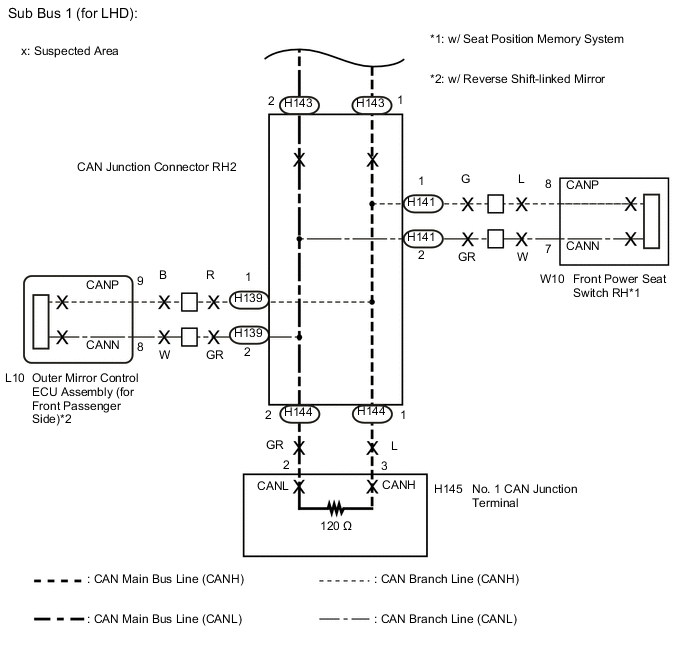
Text in Illustration *a Component without harness connected
(CAN Junction Connector RH2)
- - Wiring Color CAN Junction Connector RH2 Side Code Color (CANH Side) Color (CANL Side) CAN main bus line (bus line connecting CAN junction connector RH2 and CAN junction connector LH2) H143 B GR Outer mirror control ECU assembly (for front passenger side)*1 H139 R GR Front power seat switch RH*2 H141 G GR CAN main bus line (bus line connecting CAN junction connector RH2 and No. 1 CAN junction terminal) H144 L GR
-
*1: w/ Reverse Shift-linked Mirror
-
*2: w/ Seat Position Memory System
Note
Do not reconnect the disconnected connectors until this inspection is complete because there may be a short in 2 or more branch lines.
Result Symptom Proceed to The resistance is still below 54 Ω when all the specified connectors are disconnected. (There are no shorts between a pair of branch lines.) A The resistance becomes normal (between 54 and 69 Ω) when a connector is disconnected. (There is a short between one or more pairs of branch lines.) B -
-
When there is a short in one or more of the branch lines:
-
Reconnect all of the connectors to the CAN junction connectors, except for the one that was disconnected last (the short-circuited bus line). Check that the resistance shown on the tester is normal (between 54 and 69 Ω) to confirm that there is a short in the one branch line only.
Tech Tips
-
Connectors that connect to the CAN junction connector can be distinguished by the color of their CAN bus lines.
-
Reconnecting the connectors to non-original positions on the CAN junction connector does not affect system performance. However, it is preferred to reconnect the connectors to their original positions to avoid negative effects on the wiring such as tension on the wire harnesses, and to make future maintenance easier.
-
-
B
CHECK FOR SHORT IN SUB BUS 1 LINES (ECU, SENSOR) Click here
A
-
-
CHECK FOR SHORT IN SUB BUS 1 LINES (CAN J/C LH2)
-
Disconnect the H142 wire harness connector.
-
Text in Illustration *a Component with harness connected
(CAN Junction Connector LH2)
Measure the resistance according to the value(s) in the table below.
Standard Resistance Tester Connection Condition Specified Condition H136-1 (CANH) - H136-2 (CANL) Cable disconnected from negative (-) battery terminal 108 to 132 Ω Note
-
Before disconnecting the connector, make a note of where it is connected.
-
Reconnect the connector to its original position.
-
NG
REPLACE CAN JUNCTION CONNECTOR LH2
OK
-
-
CHECK FOR SHORT IN SUB BUS 1 LINES (CAN J/C LH2 - CAN J/C RH2)
-
Reconnect the H142 wire harness connector.
-
Disconnect the H143 wire harness connector.
-
Text in Illustration *a Component with harness connected
(CAN Junction Connector LH2)
Measure the resistance according to the value(s) in the table below.
Standard Resistance Tester Connection Condition Specified Condition H136-1 (CANH) - H136-2 (CANL) Cable disconnected from negative (-) battery terminal 108 to 132 Ω Note
-
Before disconnecting the connector, make a note of where it is connected.
-
Reconnect the connector to its original position.
-
NG
REPAIR OR REPLACE CAN MAIN BUS LINE OR CONNECTOR (CAN J/C LH2 - CAN J/C RH2)
OK
-
-
CHECK FOR SHORT IN SUB BUS 1 LINES (CAN J/C RH2)
-
Reconnect the H143 wire harness connector.
-
Disconnect the H144 wire harness connector.
-
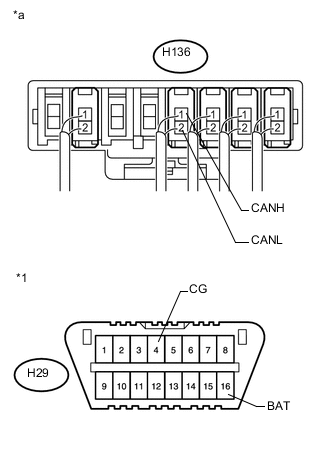
Text in Illustration *a Component with harness connected
(CAN Junction Connector LH2)
Measure the resistance according to the value(s) in the table below.
Standard Resistance Tester Connection Condition Specified Condition H136-1 (CANH) - H136-2 (CANL) Cable disconnected from negative (-) battery terminal 108 to 132 Ω Note
-
Before disconnecting the connector, make a note of where it is connected.
-
Reconnect the connector to its original position.
-
NG
REPLACE CAN JUNCTION CONNECTOR RH2
OK
-
-
CHECK FOR SHORT IN SUB BUS 1 LINES (NO. 1 CAN JUNCTION TERMINAL)
-
Reconnect the H144 wire harness connector.
-
Disconnect the H145 No. 1 CAN junction terminal.
-
Text in Illustration *a Component with harness connected
(CAN Junction Connector LH2)
Measure the resistance according to the value(s) in the table below.
Standard Resistance Tester Connection Condition Specified Condition H136-1 (CANH) - H136-2 (CANL) Cable disconnected from negative (-) battery terminal 108 to 132 Ω
OK
REPLACE NO. 1 CAN JUNCTION TERMINAL
NG
REPAIR OR REPLACE CAN MAIN BUS LINE OR CONNECTOR (CAN J/C RH2 - NO. 1 CAN JUNCTION TERMINAL)
-
-
CHECK FOR SHORT IN SUB BUS 1 LINES (ECU, SENSOR)
-
Reconnect the connector for the short-circuited branch line to the CAN junction connector (the connector that caused the bus line resistance to become normal (between 54 and 69 Ω) when it was disconnected).
-
Disconnect the connector that includes terminals CANH and CANL from the ECU to which the short-circuited branch line is connected Click here.
-
Text in Illustration *a Component with harness connected
(CAN Junction Connector LH2)
Measure the resistance according to the value(s) in the table below.
Standard Resistance Tester Connection Condition Specified Condition H136-1 (CANH) - H136-2 (CANL) Cable disconnected from negative (-) battery terminal 54 to 69 Ω Tech Tips
If the resistance becomes normal (between 54 and 69 Ω) when the connector is disconnected from the ECU, there may be a short in the ECU.
OK
REPLACE CORRESPONDING ECU OR SENSOR
NG
REPAIR OR REPLACE CORRESPONDING ECU OR SENSOR BRANCH LINES OR CONNECTOR
-
-
CHECK FOR SHORT IN SUB BUS 1 LINES (MAIN BODY ECU (MULTIPLEX NETWORK BODY ECU))
-
Reconnect the H136 wire harness connector.
-
Text in Illustration *a Front view of wire harness connector
(to Main Body ECU (Multiplex Network Body ECU))
Disconnect the H9 main body ECU (multiplex network body ECU) connector.
-
Measure the resistance according to the value(s) in the table below.
Standard Resistance Tester Connection Condition Specified Condition H9-9 (CANP) - H9-10 (CANN) Cable disconnected from negative (-) battery terminal 108 to 132 Ω
OK
REPLACE MAIN BODY ECU (MULTIPLEX NETWORK BODY ECU) Click here
NG
REPAIR OR REPLACE CAN MAIN BUS LINE OR CONNECTOR (CAN J/C LH2 - MAIN BODY ECU (MULTIPLEX NETWORK BODY ECU))
-
-
CHECK FOR SHORT IN SUB BUS 1 LINE (CAN J/C LH2 - MAIN BODY ECU (MULTIPLEX NETWORK BODY ECU))
-
Disconnect the H136 wire harness connector.
-
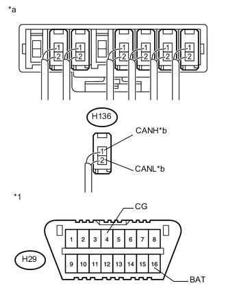
Text in Illustration *1 DLC3 *a Rear view of wire harness connector
(to CAN Junction Connector LH2)
*b to Main Body ECU (Multiplex Network Body ECU) Measure the resistance according to the value(s) in the table below.
Standard Resistance Tester Connection Condition Specified Condition Result H136-1 (CANH) - H29-4 (CG) Cable disconnected from negative (-) battery terminal 200 Ω or higher Below 200 Ω:
CANH ground short
H136-2 (CANL) - H29-4 (CG) Cable disconnected from negative (-) battery terminal 200 Ω or higher Below 200 Ω:
CANL ground short
H136-1 (CANH) - H29-16 (BAT) Cable disconnected from negative (-) battery terminal 6 kΩ or higher Below 6 kΩ:
CANH +B short
H136-2 (CANL) - H29-16 (BAT) Cable disconnected from negative (-) battery terminal 6 kΩ or higher Below 6 kΩ:
CANL +B short
Note
-
Before disconnecting the connector, make a note of where it is connected.
-
Reconnect the connector to its original position.
Tech Tips
-
It is only necessary to perform the inspection in the above table for the result (short circuit) that was obtained in the Check Sub Bus 1 inspection.
-
Find the necessary inspection from the Result column that matches the result in the Specified Condition column from the Check Sub Bus 1 inspection.
-
NG
CHECK FOR SHORT IN SUB BUS 1 LINE (MAIN BODY ECU (MULTIPLEX NETWORK BODY ECU)) Click here
OK
-
-
CHECK FOR SHORT IN SUB BUS 1 LINE (BRANCH LINE)
-
Reconnect the H136 wire harness connector.
-
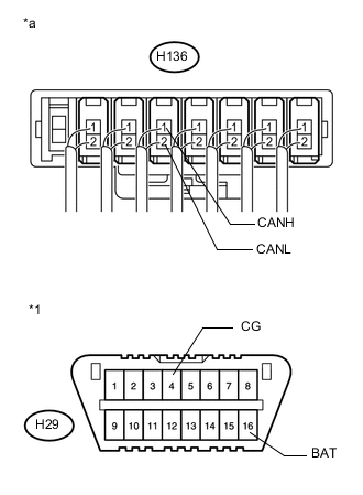
Text in Illustration *1 DLC3 *a Component with harness connected
(CAN Junction Connector LH2)
Connect the probes of an ohmmeter to terminals 1 (CANH) and 2 (CANL) of the wire harness connector (H136) and CG or BAT of the DLC3.
Tech Tips
It is only necessary to perform the inspection for the result (short circuit) that was obtained in the Check Sub Bus 1 inspection.
-
While observing the resistance value shown on the ohmmeter, disconnect branch line connectors (H135, H137, H138, H139, H140, H141 and H185) from the CAN junction connector LH2 or CAN junction connector RH2 until the resistance becomes normal (6 kΩ or higher (for +B short) or 200 Ω or higher (for ground short)).
Text in Illustration *A w/ Parking Assist Monitor System without Parallel Parking Assist Function *B w/ Power Trunk Lid System *C w/ Power Tilt and Power Telescopic Steering Column System *D w/ Seat Position Memory System *1 Rear Television Camera Assembly *2 Luggage Closer Motor Assembly *3 Main Body ECU (Multiplex Network Body ECU) *4 Multiplex Tilt and Telescopic ECU *5 Outer Mirror Control ECU Assembly (for Driver Side)
(w/ Reverse Shift-linked Mirror)
*6 Front Power Seat Switch LH *7 CAN Junction Connector LH2 *8 Outer Mirror Control ECU Assembly (for Front Passenger Side)
(w/ Reverse Shift-linked Mirror)
*9 Front Power Seat Switch RH *10 No. 1 CAN Junction Terminal *11 CAN Junction Connector RH2 - -
Text in Illustration *a Component without harness connected
(CAN Junction Connector LH2)
- - Wiring Color CAN Junction Connector LH2 Side Code Color (CANH Side) Color (CANL Side) Rear television camera assembly*1 H185 P GR Luggage closer motor assembly*2 H135 V GR Main body ECU (multiplex network body ECU) H136 Y GR Multiplex tilt and telescopic ECU*3 H137 L GR Outer mirror control ECU assembly (for driver side)*4 H138 G GR Front power seat switch LH*5 H140 R GR CAN main bus line (bus line connecting CAN junction connector LH2 and CAN junction connector RH2) H142 B GR
-
*1: w/ Parking Assist Monitor System without Parallel Parking Assist Function
-
*2: w/ Power Trunk Lid System
-
*3: w/ Power Tilt and Power Telescopic Steering Column System
-
*4: w/ Reverse Shift-linked Mirror
-
*5: w/ Seat Position Memory System
Text in Illustration *a Component without harness connected
(CAN Junction Connector RH2)
- - Wiring Color CAN Junction Connector RH2 Side Code Color (CANH Side) Color (CANL Side) CAN main bus line (bus line connecting CAN junction connector RH2 and CAN junction connector LH2) H143 B GR Outer mirror control ECU assembly (for front passenger side)*1 H139 R GR Front power seat switch RH*2 H141 G GR CAN main bus line (bus line connecting CAN junction connector RH2 and No. 1 CAN junction terminal) H144 L GR
-
*1: w/ Reverse Shift-linked Mirror
-
*2: w/ Seat Position Memory System
Result Result Proceed to The resistance between terminals CANP and BAT, or the resistance between terminals CANN and BAT is still below 6 kΩ when all the specified connectors are disconnected from the CAN junction connector.
(There is no short to +B in the branch lines.)
A The resistance between terminals CANP and GND, or the resistance between terminals CANN and GND is still below 200 Ω when all the specified connectors are disconnected from the CAN junction connector.
(There is no short to GND in the branch lines.)
The resistance between terminals CANP and BAT, or the resistance between terminals CANN and BAT becomes normal (6 kΩ or higher) when a connector is disconnected from the CAN junction connector.
(There is a short to +B in one of the areas related to one or more of the disconnected branch lines.)
B The resistance between terminals CANP and GND, or the resistance between terminals CANN and GND becomes normal (200 Ω or higher) when a connector is disconnected from the CAN junction connector.
(There is a short to GND in one of the areas related to one or more of the disconnected branch lines.)
-
B
CHECK FOR SHORT IN SUB BUS 1 LINE (ECU, SENSOR) Click here
A
-
-
CHECK FOR SHORT IN SUB BUS 1 LINE (CAN J/C LH2)
-
Disconnect the H142 wire harness connector.
-
Text in Illustration *1 DLC3 *a Component with harness connected
(CAN Junction Connector LH2)
Measure the resistance according to the value(s) in the table below.
Standard Resistance Tester Connection Condition Specified Condition Result H136-1 (CANH) - H29-4 (CG) Cable disconnected from negative (-) battery terminal 200 Ω or higher Below 200 Ω:
CANH ground short
H136-2 (CANL) - H29-4 (CG) Cable disconnected from negative (-) battery terminal 200 Ω or higher Below 200 Ω:
CANL ground short
H136-1 (CANH) - H29-16 (BAT) Cable disconnected from negative (-) battery terminal 6 kΩ or higher Below 6 kΩ:
CANH +B short
H136-2 (CANL) - H29-16 (BAT) Cable disconnected from negative (-) battery terminal 6 kΩ or higher Below 6 kΩ:
CANL +B short
Note
-
Before disconnecting the connector, make a note of where it is connected.
-
Reconnect the connector to its original position.
Tech Tips
-
It is only necessary to perform the inspection in the above table for the result (short circuit) that was obtained in the Check Sub Bus 1 inspection.
-
Find the necessary inspection from the Result column that matches the result in the Specified Condition column from the Check Sub Bus 1 inspection.
-
NG
REPLACE CAN JUNCTION CONNECTOR LH2
OK
-
-
CHECK FOR SHORT IN SUB BUS 1 LINE (CAN J/C LH2 - CAN J/C RH2)
-
Reconnect the H142 wire harness connector.
-
Disconnect the H143 wire harness connector.
-
Text in Illustration *1 DLC3 *a Component with harness connected
(CAN Junction Connector LH2)
Measure the resistance according to the value(s) in the table below.
Standard Resistance Tester Connection Condition Specified Condition Result H136-1 (CANH) - H29-4 (CG) Cable disconnected from negative (-) battery terminal 200 Ω or higher Below 200 Ω:
CANH ground short
H136-2 (CANL) - H29-4 (CG) Cable disconnected from negative (-) battery terminal 200 Ω or higher Below 200 Ω:
CANL ground short
H136-1 (CANH) - H29-16 (BAT) Cable disconnected from negative (-) battery terminal 6 kΩ or higher Below 6 kΩ:
CANH +B short
H136-2 (CANL) - H29-16 (BAT) Cable disconnected from negative (-) battery terminal 6 kΩ or higher Below 6 kΩ:
CANL +B short
Note
-
Before disconnecting the connector, make a note of where it is connected.
-
Reconnect the connector to its original position.
Tech Tips
-
It is only necessary to perform the inspection in the above table for the result (short circuit) that was obtained in the Check Sub Bus 1 inspection.
-
Find the necessary inspection from the Result column that matches the result in the Specified Condition column from the Check Sub Bus 1 inspection.
-
NG
REPAIR OR REPLACE CAN MAIN BUS LINE OR CONNECTOR (CAN J/C LH2 - CAN J/C RH2)
OK
-
-
CHECK FOR SHORT IN SUB BUS 1 LINE (CAN J/C RH2)
-
Reconnect the H143 wire harness connector.
-
Disconnect the H144 wire harness connector.
-
Text in Illustration *1 DLC3 *a Component with harness connected
(CAN Junction Connector LH2)
Measure the resistance according to the value(s) in the table below.
Standard Resistance Tester Connection Condition Specified Condition Result H136-1 (CANH) - H29-4 (CG) Cable disconnected from negative (-) battery terminal 200 Ω or higher Below 200 Ω:
CANH ground short
H136-2 (CANL) - H29-4 (CG) Cable disconnected from negative (-) battery terminal 200 Ω or higher Below 200 Ω:
CANL ground short
H136-1 (CANH) - H29-16 (BAT) Cable disconnected from negative (-) battery terminal 6 kΩ or higher Below 6 kΩ:
CANH +B short
H136-2 (CANL) - H29-16 (BAT) Cable disconnected from negative (-) battery terminal 6 kΩ or higher Below 6 kΩ:
CANL +B short
Note
-
Before disconnecting the connector, make a note of where it is connected.
-
Reconnect the connector to its original position.
Tech Tips
-
It is only necessary to perform the inspection in the above table for the result (short circuit) that was obtained in the Check Sub Bus 1 inspection.
-
Find the necessary inspection from the Result column that matches the result in the Specified Condition column from the Check Sub Bus 1 inspection.
-
NG
REPLACE CAN JUNCTION CONNECTOR RH2
OK
-
-
CHECK FOR SHORT IN SUB BUS 1 LINE (NO. 1 CAN JUNCTION TERMINAL)
-
Reconnect the H144 wire harness connector.
-
Disconnect the H145 No. 1 CAN junction terminal.
-
Text in Illustration *1 DLC3 *a Component with harness connected
(CAN Junction Connector LH2)
Measure the resistance according to the value(s) in the table below.
Standard Resistance Tester Connection Condition Specified Condition Result H136-1 (CANH) - H29-4 (CG) Cable disconnected from negative (-) battery terminal 200 Ω or higher Below 200 Ω:
CANH ground short
H136-2 (CANL) - H29-4 (CG) Cable disconnected from negative (-) battery terminal 200 Ω or higher Below 200 Ω:
CANL ground short
H136-1 (CANH) - H29-16 (BAT) Cable disconnected from negative (-) battery terminal 6 kΩ or higher Below 6 kΩ:
CANH +B short
H136-2 (CANL) - H29-16 (BAT) Cable disconnected from negative (-) battery terminal 6 kΩ or higher Below 6 kΩ:
CANL +B short
Tech Tips
-
It is only necessary to perform the inspection in the above table for the result (short circuit) that was obtained in the Check Sub Bus 1 inspection.
-
Find the necessary inspection from the Result column that matches the result in the Specified Condition column from the Check Sub Bus 1 inspection.
-
OK
REPLACE NO. 1 CAN JUNCTION TERMINAL
NG
REPAIR OR REPLACE CAN MAIN BUS LINE OR CONNECTOR (CAN J/C RH2 - NO. 1 CAN JUNCTION TERMINAL)
-
-
CHECK FOR SHORT IN SUB BUS 1 LINE (ECU, SENSOR)
-
Reconnect the connector for the bus line that is shorted to +B or GND to the CAN junction connector (the connector that caused the bus line resistance to change to 6 kΩ or higher (for +B short) or 200 Ω or higher (for ground short) when it was disconnected).
-
Disconnect the connector that includes terminals CANH and CANL from the ECU to which the bus line shorted to +B or GND is connected Click here.
-
Text in Illustration *1 DLC3 *a Component with harness connected
(CAN Junction Connector LH2)
Measure the resistance according to the value(s) in the table below.
Standard Resistance Tester Connection Condition Specified Condition Result H136-1 (CANH) - H29-4 (CG) Cable disconnected from negative (-) battery terminal 200 Ω or higher Below 200 Ω:
CANH ground short
H136-2 (CANL) - H29-4 (CG) Cable disconnected from negative (-) battery terminal 200 Ω or higher Below 200 Ω:
CANL ground short
H136-1 (CANH) - H29-16 (BAT) Cable disconnected from negative (-) battery terminal 6 kΩ or higher Below 6 kΩ:
CANH +B short
H136-2 (CANL) - H29-16 (BAT) Cable disconnected from negative (-) battery terminal 6 kΩ or higher Below 6 kΩ:
CANL +B short
Tech Tips
-
It is only necessary to perform the inspection in the above table for the result (short circuit) that was obtained in the Check Sub Bus 1 inspection.
-
If the resistance becomes normal when the connector is disconnected from the ECU, there may be a short in the ECU.
-
OK
REPLACE CORRESPONDING ECU OR SENSOR
NG
REPAIR OR REPLACE CORRESPONDING ECU OR SENSOR BRANCH LINES OR CONNECTOR
-
-
CHECK FOR SHORT IN SUB BUS 1 LINE (MAIN BODY ECU (MULTIPLEX NETWORK BODY ECU))
-
Disconnect the H9 main body ECU (multiplex network body ECU) connector.
-
Text in Illustration *1 DLC3 *a Rear view of wire harness connector
(to CAN Junction Connector LH2)
Measure the resistance according to the value(s) in the table below.
Standard Resistance Tester Connection Condition Specified Condition Result H136-1 (CANH) - H29-4 (CG) Cable disconnected from negative (-) battery terminal 200 Ω or higher Below 200 Ω:
CANH ground short
H136-2 (CANL) - H29-4 (CG) Cable disconnected from negative (-) battery terminal 200 Ω or higher Below 200 Ω:
CANL ground short
H136-1 (CANH) - H29-16 (BAT) Cable disconnected from negative (-) battery terminal 6 kΩ or higher Below 6 kΩ:
CANH +B short
H136-2 (CANL) - H29-16 (BAT) Cable disconnected from negative (-) battery terminal 6 kΩ or higher Below 6 kΩ:
CANL +B short
Tech Tips
-
It is only necessary to perform the inspection in the above table for the result (short circuit) that was obtained in the Check Sub Bus 1 inspection.
-
Find the necessary inspection from the Result column that matches the result in the Specified Condition column from the Check Sub Bus 1 inspection.
-
OK
REPLACE MAIN BODY ECU (MULTIPLEX NETWORK BODY ECU) Click here
NG
REPAIR OR REPLACE CAN MAIN BUS LINE OR CONNECTOR (CAN J/C LH2 - MAIN BODY ECU (MULTIPLEX NETWORK BODY ECU))
-
-
CHECK SUB BUS 1
-
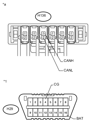
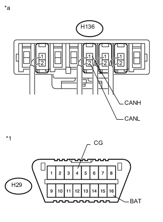
Text in Illustration *1 DLC3 *a Component with harness connected
(CAN Junction Connector LH2)
Disconnect the cable from the negative (-) battery terminal.
-
Measure the resistance according to the value(s) in the table below.
Standard Resistance Tester Connection Condition Specified Condition Result H136-1 (CANH) - H136-2 (CANL) Cable disconnected from negative (-) battery terminal 54 to 69 Ω Below 54 Ω:
Short circuit between bus lines
70 Ω or higher:
Open circuit in a main bus line
H136-1 (CANH) - H29-4 (CG) Cable disconnected from negative (-) battery terminal 200 Ω or higher Below 200 Ω:
CANH ground short
H136-2 (CANL) - H29-4 (CG) Cable disconnected from negative (-) battery terminal 200 Ω or higher Below 200 Ω:
CANL ground short
H136-1 (CANH) - H29-16 (BAT) Cable disconnected from negative (-) battery terminal 6 kΩ or higher Below 6 kΩ:
CANH +B short
H136-2 (CANL) - H29-16 (BAT) Cable disconnected from negative (-) battery terminal 6 kΩ or higher Below 6 kΩ:
CANL +B short
Result Result Proceed to OK A Open circuit in CAN main bus line B Short circuit between bus lines C
-
Ground short
-
+B short
D -
B
CHECK FOR OPEN IN SUB BUS 1 LINES (CAN J/C LH2 - MAIN BODY ECU (MULTIPLEX NETWORK BODY ECU)) Click here
C
CHECK FOR SHORT IN SUB BUS 1 LINES (CAN J/C LH2 - MAIN BODY ECU (MULTIPLEX NETWORK BODY ECU)) Click here
D
CHECK FOR SHORT IN SUB BUS 1 LINE (CAN J/C LH2 - MAIN BODY ECU (MULTIPLEX NETWORK BODY ECU)) Click here
A
-
-
RECONFIRM DTC OUTPUT
-
Reconnect the cable to the negative (-) battery terminal.
-
Connect the GTS to the DLC3.
-
Turn the engine switch on (IG).
-
Turn the GTS on.
-
Clear the DTCs.
-
Turn the engine switch off.
-
Turn the engine switch on (IG) and recheck for DTCs.
Result Result Proceed to U1002 is output from main body ECU (multiplex network body ECU)
(GTS display: Main Body)
A Other DTC is output B
A
REPLACE MAIN BODY ECU (MULTIPLEX NETWORK BODY ECU) Click here
B
GO TO DIAGNOSIS PROCEDURE INDICATED BY OUTPUT DTC Click here
-
-
CHECK FOR OPEN IN SUB BUS 1 LINES (CAN J/C LH2 - MAIN BODY ECU (MULTIPLEX NETWORK BODY ECU))
-
Disconnect the H136 wire harness connector.
-
Text in Illustration *a Rear view of wire harness connector
(to CAN Junction Connector LH2)
*b to Main Body ECU (Multiplex Network Body ECU) Measure the resistance according to the value(s) in the table below.
Standard Resistance Tester Connection Condition Specified Condition H136-1 (CANH) - H136-2 (CANL) Cable disconnected from negative (-) battery terminal 108 to 132 Ω Note
-
Before disconnecting the connector, make a note of where it is connected.
-
Reconnect the connector to its original position.
-
NG
CHECK FOR OPEN IN SUB BUS 1 MAIN LINES (MAIN BODY ECU (MULTIPLEX NETWORK BODY ECU)) Click here
OK
-
-
CHECK FOR OPEN IN SUB BUS 1 LINES (CAN J/C LH2)
-
Reconnect the H136 wire harness connector.
-
Text in Illustration *a Rear view of wire harness connector
(to CAN Junction Connector LH2)
*b to CAN Junction Connector RH2 Disconnect the H142 wire harness connector.
-
Measure the resistance according to the value(s) in the table below.
Standard Resistance Tester Connection Condition Specified Condition H142-1 (CANH) - H142-2 (CANL) Cable disconnected from negative (-) battery terminal 108 to 132 Ω Note
-
Before disconnecting the connector, make a note of where it is connected.
-
Reconnect the connector to its original position.
-
OK
REPLACE CAN JUNCTION CONNECTOR LH2
NG
-
-
CHECK FOR OPEN IN SUB BUS 1 LINES (CAN J/C LH2 - CAN J/C RH2)
-
Reconnect the H142 wire harness connector.
-
Text in Illustration *a Rear view of wire harness connector
(to CAN Junction Connector RH2)
*b to CAN Junction Connector LH2 Disconnect the H143 wire harness connector.
-
Measure the resistance according to the value(s) in the table below.
Standard Resistance Tester Connection Condition Specified Condition H143-1 (CANH) - H143-2 (CANL) Cable disconnected from negative (-) battery terminal 108 to 132 Ω Note
-
Before disconnecting the connector, make a note of where it is connected.
-
Reconnect the connector to its original position.
-
NG
REPAIR OR REPLACE CAN MAIN BUS LINE OR CONNECTOR (CAN J/C LH2 - CAN J/C RH2)
OK
-
-
CHECK FOR OPEN IN SUB BUS 1 MAIN LINES (CAN J/C RH2)
-
Reconnect the H143 wire harness connector.
-
Text in Illustration *a Rear view of wire harness connector
(to CAN Junction Connector RH2)
*b to No. 1 CAN Junction Terminal Disconnect the H144 wire harness connector.
-
Measure the resistance according to the value(s) in the table below.
Standard Resistance Tester Connection Condition Specified Condition H144-1 (CANH) - H144-2 (CANL) Cable disconnected from negative (-) battery terminal 108 to 132 Ω Note
-
Before disconnecting the connector, make a note of where it is connected.
-
Reconnect the connector to its original position.
-
OK
REPLACE CAN JUNCTION CONNECTOR RH2
NG
-
-
CHECK FOR OPEN IN SUB BUS 1 MAIN LINES (NO. 1 CAN JUNCTION TERMINAL)
-
Reconnect the H144 wire harness connector.
-
Text in Illustration *a Rear view of wire harness connector
(to No. 1 CAN Junction Terminal)
*b to CAN Junction Connector RH2 Disconnect the H145 No. 1 CAN junction terminal.
-
Measure the resistance according to the value(s) in the table below.
Standard Resistance Tester Connection Condition Specified Condition H145-3 (CANH) - H145-2 (CANL) Cable disconnected from negative (-) battery terminal 108 to 132 Ω
OK
REPLACE NO. 1 CAN JUNCTION TERMINAL
NG
REPAIR OR REPLACE CAN MAIN BUS LINE OR CONNECTOR (CAN J/C RH2 - NO. 1 CAN JUNCTION TERMINAL)
-
-
CHECK FOR OPEN IN SUB BUS 1 MAIN LINES (MAIN BODY ECU (MULTIPLEX NETWORK BODY ECU))
-
Reconnect the H136 wire harness connector.
-
Text in Illustration *a Front view of wire harness connector
(to Main Body ECU (Multiplex Network Body ECU))
Disconnect the H9 main body ECU (multiplex network body ECU) connector.
-
Measure the resistance according to the value(s) in the table below.
Standard Resistance Tester Connection Condition Specified Condition H9-9 (CANP) - H9-10 (CANN) Cable disconnected from negative (-) battery terminal 108 to 132 Ω
OK
REPLACE MAIN BODY ECU (MULTIPLEX NETWORK BODY ECU) Click here
NG
REPAIR OR REPLACE CAN MAIN BUS LINE OR CONNECTOR (CAN J/C LH2 - MAIN BODY ECU (MULTIPLEX NETWORK BODY ECU))
-
-
CHECK FOR SHORT IN SUB BUS 1 LINES (CAN J/C LH2 - MAIN BODY ECU (MULTIPLEX NETWORK BODY ECU))
-
Disconnect the H136 wire harness connector.
-

Text in Illustration *a Rear view of wire harness connector
(to CAN Junction Connector LH2)
*b to Main Body ECU (Multiplex Network Body ECU) Measure the resistance according to the value(s) in the table below.
Standard Resistance Tester Connection Condition Specified Condition H136-1 (CANH) - H136-2 (CANL) Cable disconnected from negative (-) battery terminal 108 to 132 Ω Note
-
Before disconnecting the connector, make a note of where it is connected.
-
Reconnect the connector to its original position.
-
NG
CHECK FOR SHORT IN SUB BUS 1 LINES (MAIN BODY ECU (MULTIPLEX NETWORK BODY ECU)) Click here
OK
-
-
CHECK FOR SHORT IN SUB BUS 1 LINES (BRANCH LINE)
-
Reconnect the H136 wire harness connector.
-
Text in Illustration *a Component with harness connected
(CAN Junction Connector LH2)
Connect the probes of an ohmmeter to terminals 1 (CANH) and 2 (CANL) of the main body ECU (multiplex network body ECU) main line harness connector.
-
While observing the resistance value shown on the tester, disconnect connectors (H135, H137, H138, H139, H140, H141 and H185) from the CAN junction connector LH2 or CAN junction connector RH2 one by one until the resistance becomes normal (between 54 and 69 Ω).
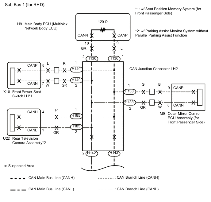
Text in Illustration *A w/ Seat Position Memory System (for Front Passenger Side) *B w/ Power Tilt and Power Telescopic Steering Column System *C w/ Power Trunk Lid System *D w/ Parking Assist Monitor System without Parallel Parking Assist Function *1 No. 1 CAN Junction Terminal *2 Front Power Seat Switch RH *3 Outer Mirror Control ECU Assembly (for Driver Side) *4 Multiplex Tilt and Telescopic ECU *5 Luggage Closer Motor Assembly *6 CAN Junction Connector RH2 *7 Front Power Seat Switch LH *8 Outer Mirror Control ECU Assembly (for Front Passenger Side) *9 Main Body ECU (Multiplex Network Body ECU) *10 Rear Television Camera Assembly *11 CAN Junction Connector LH2 - - 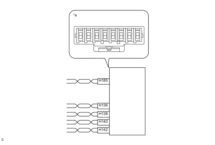
Text in Illustration *a Component without harness connected
(CAN Junction Connector LH2)
- - Wiring Color CAN Junction Connector LH2 Side Code Color (CANH Side) Color (CANL Side) Rear television camera assembly*1 H185 P GR Main body ECU (multiplex network body ECU) H136 L GR Outer mirror control ECU assembly (for front passenger side) H138 G GR Front power seat switch LH*2 H140 R GR CAN main bus line (bus line connecting CAN junction connector RH2 and CAN junction connector LH2) H142 B GR
-
*1: w/ Parking Assist Monitor System without Parallel Parking Assist Function
-
*2: w/ Seat Position Memory System (for Front Passenger Side)
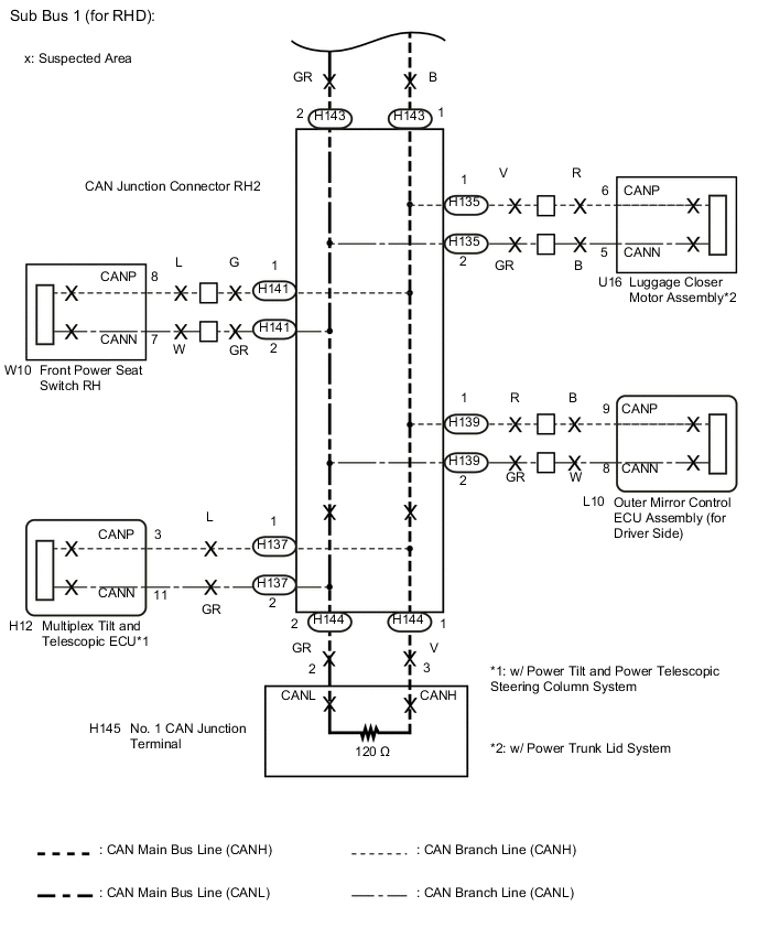
Text in Illustration *a Component without harness connected
(CAN Junction Connector RH2)
- - Wiring Color CAN Junction Connector RH2 Side Code Color (CANH Side) Color (CANL Side) CAN main bus line (bus line connecting CAN junction connector LH2 and CAN junction connector RH2) H143 B GR Outer mirror control ECU assembly (for driver side) H139 R GR Front power seat switch RH H141 G GR Multiplex tilt and telescopic ECU*1 H137 L GR Luggage closer motor assembly*2 H135 V GR CAN main bus line (bus line connecting CAN junction connector LH2 and No. 1 CAN junction terminal) H144 V GR
-
*1: w/ Power Tilt and Power Telescopic Steering Column System
-
*2: w/ Power Trunk Lid System
Note
Do not reconnect the disconnected connectors until this inspection is complete because there may be a short in 2 or more branch lines.
Result Symptom Proceed to The resistance is still below 54 Ω when all the specified connectors are disconnected. (There are no shorts between a pair of branch lines.) A The resistance becomes normal (between 54 and 69 Ω) when a connector is disconnected. (There is a short between one or more pairs of branch lines.) B -
-
When there is a short in one or more of the branch lines:
-
Reconnect all of the connectors to the CAN junction connectors, except for the one that was disconnected last (the short-circuited bus line). Check that the resistance shown on the tester is normal (between 54 and 69 Ω) to confirm that there is a short in the one branch line only.
Tech Tips
-
Connectors that connect to the CAN junction connector can be distinguished by the color of their CAN bus lines.
-
Reconnecting the connectors to non-original positions on the CAN junction connector does not affect system performance. However, it is preferred to reconnect the connectors to their original positions to avoid negative effects on the wiring such as tension on the wire harnesses, and to make future maintenance easier.
-
-
B
CHECK FOR SHORT IN SUB BUS 1 LINES (ECU, SENSOR) Click here
A
-
-
CHECK FOR SHORT IN SUB BUS 1 LINES (CAN J/C LH2)
-
Disconnect the H142 wire harness connector.
-
Text in Illustration *a Component with harness connected
(CAN Junction Connector LH2)
Measure the resistance according to the value(s) in the table below.
Standard Resistance Tester Connection Condition Specified Condition H136-1 (CANH) - H136-2 (CANL) Cable disconnected from negative (-) battery terminal 108 to 132 Ω Note
-
Before disconnecting the connector, make a note of where it is connected.
-
Reconnect the connector to its original position.
-
NG
REPLACE CAN JUNCTION CONNECTOR LH2
OK
-
-
CHECK FOR SHORT IN SUB BUS 1 LINES (CAN J/C LH2 - CAN J/C RH2)
-
Reconnect the H142 wire harness connector.
-
Disconnect the H143 wire harness connector.
-
Text in Illustration *a Component with harness connected
(CAN Junction Connector LH2)
Measure the resistance according to the value(s) in the table below.
Standard Resistance Tester Connection Condition Specified Condition H136-1 (CANH) - H136-2 (CANL) Cable disconnected from negative (-) battery terminal 108 to 132 Ω Note
-
Before disconnecting the connector, make a note of where it is connected.
-
Reconnect the connector to its original position.
-
NG
REPAIR OR REPLACE CAN MAIN BUS LINE OR CONNECTOR (CAN J/C LH2 - CAN J/C RH2)
OK
-
-
CHECK FOR SHORT IN SUB BUS 1 LINES (CAN J/C RH2)
-
Reconnect the H143 wire harness connector.
-
Disconnect the H144 wire harness connector.
-
Text in Illustration *a Component with harness connected
(CAN Junction Connector LH2)
Measure the resistance according to the value(s) in the table below.
Standard Resistance Tester Connection Condition Specified Condition H136-1 (CANH) - H136-2 (CANL) Cable disconnected from negative (-) battery terminal 108 to 132 Ω Note
-
Before disconnecting the connector, make a note of where it is connected.
-
Reconnect the connector to its original position.
-
NG
REPLACE CAN JUNCTION CONNECTOR RH2
OK
-
-
CHECK FOR SHORT IN SUB BUS 1 LINES (NO. 1 CAN JUNCTION TERMINAL)
-
Reconnect the H144 wire harness connector.
-
Disconnect the H145 No. 1 CAN junction terminal.
-
Text in Illustration *a Component with harness connected
(CAN Junction Connector LH2)
Measure the resistance according to the value(s) in the table below.
Standard Resistance Tester Connection Condition Specified Condition H136-1 (CANH) - H136-2 (CANL) Cable disconnected from negative (-) battery terminal 108 to 132 Ω
OK
REPLACE NO. 1 CAN JUNCTION TERMINAL
NG
REPAIR OR REPLACE CAN MAIN BUS LINE OR CONNECTOR (CAN J/C RH2 - NO. 1 CAN JUNCTION TERMINAL)
-
-
CHECK FOR SHORT IN SUB BUS 1 LINES (ECU, SENSOR)
-
Reconnect the connector for the short-circuited branch line to the CAN junction connector (the connector that caused the bus line resistance to become normal (between 54 and 69 Ω) when it was disconnected).
-
Disconnect the connector that includes terminals CANH and CANL from the ECU to which the short-circuited branch line is connected Click here.
-
Text in Illustration *a Component with harness connected
(CAN Junction Connector LH2)
Measure the resistance according to the value(s) in the table below.
Standard Resistance Tester Connection Condition Specified Condition H136-1 (CANH) - H136-2 (CANL) Cable disconnected from negative (-) battery terminal 54 to 69 Ω Tech Tips
If the resistance becomes normal (between 54 and 69 Ω) when the connector is disconnected from the ECU, there may be a short in the ECU.
OK
REPLACE CORRESPONDING ECU OR SENSOR
NG
REPAIR OR REPLACE CORRESPONDING ECU OR SENSOR BRANCH LINES OR CONNECTOR
-
-
CHECK FOR SHORT IN SUB BUS 1 LINES (MAIN BODY ECU (MULTIPLEX NETWORK BODY ECU))
-
Reconnect the H136 wire harness connector.
-
Text in Illustration *a Front view of wire harness connector
(to Main Body ECU (Multiplex Network Body ECU))
Disconnect the H9 main body ECU (multiplex network body ECU) connector.
-
Measure the resistance according to the value(s) in the table below.
Standard Resistance Tester Connection Condition Specified Condition H9-9 (CANP) - H9-10 (CANN) Cable disconnected from negative (-) battery terminal 108 to 132 Ω
OK
REPLACE MAIN BODY ECU (MULTIPLEX NETWORK BODY ECU) Click here
NG
REPAIR OR REPLACE CAN MAIN BUS LINE OR CONNECTOR (CAN J/C LH2 - MAIN BODY ECU (MULTIPLEX NETWORK BODY ECU))
-
-
CHECK FOR SHORT IN SUB BUS 1 LINE (CAN J/C LH2 - MAIN BODY ECU (MULTIPLEX NETWORK BODY ECU))
-
Disconnect the H136 wire harness connector.
-
Text in Illustration *1 DLC3 *a Rear view of wire harness connector
(to CAN Junction Connector LH2)
*b to Main Body ECU (Multiplex Network Body ECU) Measure the resistance according to the value(s) in the table below.
Standard Resistance Tester Connection Condition Specified Condition Result H136-1 (CANH) - H29-4 (CG) Cable disconnected from negative (-) battery terminal 200 Ω or higher Below 200 Ω:
CANH ground short
H136-2 (CANL) - H29-4 (CG) Cable disconnected from negative (-) battery terminal 200 Ω or higher Below 200 Ω:
CANL ground short
H136-1 (CANH) - H29-16 (BAT) Cable disconnected from negative (-) battery terminal 6 kΩ or higher Below 6 kΩ:
CANH +B short
H136-2 (CANL) - H29-16 (BAT) Cable disconnected from negative (-) battery terminal 6 kΩ or higher Below 6 kΩ:
CANL +B short
Note
-
Before disconnecting the connector, make a note of where it is connected.
-
Reconnect the connector to its original position.
Tech Tips
-
It is only necessary to perform the inspection in the above table for the result (short circuit) that was obtained in the Check Sub Bus 1 inspection.
-
Find the necessary inspection from the Result column that matches the result in the Specified Condition column from the Check Sub Bus 1 inspection.
-
NG
CHECK FOR SHORT IN SUB BUS 1 LINE (MAIN BODY ECU (MULTIPLEX NETWORK BODY ECU)) Click here
OK
-
-
CHECK FOR SHORT IN SUB BUS 1 LINE (BRANCH LINE)
-
Reconnect the H136 wire harness connector.
-
Text in Illustration *1 DLC3 *a Component with harness connected
(CAN Junction Connector LH2)
Connect the probes of an ohmmeter to terminals 1 (CANH) and 2 (CANL) of the wire harness connector (H136) and CG or BAT of the DLC3.
Tech Tips
It is only necessary to perform the inspection for the result (short circuit) that was obtained in the Check Sub Bus 1 inspection.
-
While observing the resistance value shown on the ohmmeter, disconnect branch line connectors (H135, H137, H138, H139, H140, H141 and H185) from the CAN junction connector LH2 or CAN junction connector RH2 until the resistance becomes normal (6 kΩ or higher (for +B short) or 200 Ω or higher (for ground short)).
Text in Illustration *A w/ Seat Position Memory System (for Front Passenger Side) *B w/ Power Tilt and Power Telescopic Steering Column System *C w/ Power Trunk Lid System *D w/ Parking Assist Monitor System without Parallel Parking Assist Function *1 No. 1 CAN Junction Terminal *2 Front Power Seat Switch RH *3 Outer Mirror Control ECU Assembly (for Driver Side) *4 Multiplex Tilt and Telescopic ECU *5 Luggage Closer Motor Assembly *6 CAN Junction Connector RH2 *7 Front Power Seat Switch LH *8 Outer Mirror Control ECU Assembly (for Front Passenger Side) *9 Main Body ECU (Multiplex Network Body ECU) *10 Rear Television Camera Assembly *11 CAN Junction Connector LH2 - -
Text in Illustration *a Component without harness connected
(CAN Junction Connector LH2)
- - Wiring Color CAN Junction Connector LH2 Side Code Color (CANH Side) Color (CANL Side) Rear television camera assembly*1 H185 P GR Main body ECU (multiplex network body ECU) H136 L GR Outer mirror control ECU assembly (for front passenger side) H138 G GR Front power seat switch LH*2 H140 R GR CAN main bus line (bus line connecting CAN junction connector RH2 and CAN junction connector LH2) H142 B GR
-
*1: w/ Parking Assist Monitor System without Parallel Parking Assist Function
-
*2: w/ Seat Position Memory System (for Front Passenger Side)
Text in Illustration *a Component without harness connected
(CAN Junction Connector RH2)
- - Wiring Color CAN Junction Connector RH2 Side Code Color (CANH Side) Color (CANL Side) CAN main bus line (bus line connecting CAN junction connector LH2 and CAN junction connector RH2) H143 B GR Outer mirror control ECU assembly (for driver side) H139 R GR Front power seat switch RH H141 G GR Multiplex tilt and telescopic ECU*1 H137 L GR Luggage closer motor assembly*2 H135 V GR CAN main bus line (bus line connecting CAN junction connector LH2 and No. 1 CAN junction terminal) H144 V GR
-
*1: w/ Power Tilt and Power Telescopic Steering Column System
-
*2: w/ Power Trunk Lid System
Result Result Proceed to The resistance between terminals CANP and BAT, or the resistance between terminals CANN and BAT is still below 6 kΩ when all the specified connectors are disconnected from the CAN junction connector.
(There is no short to +B in the branch lines.)
A The resistance between terminals CANP and GND, or the resistance between terminals CANN and GND is still below 200 Ω when all the specified connectors are disconnected from the CAN junction connector.
(There is no short to GND in the branch lines.)
The resistance between terminals CANP and BAT, or the resistance between terminals CANN and BAT becomes normal (6 kΩ or higher) when a connector is disconnected from the CAN junction connector.
(There is a short to +B in one of the areas related to one or more of the disconnected branch lines.)
B The resistance between terminals CANP and GND, or the resistance between terminals CANN and GND becomes normal (200 Ω or higher) when a connector is disconnected from the CAN junction connector.
(There is a short to GND in one of the areas related to one or more of the disconnected branch lines.)
-
B
CHECK FOR SHORT IN SUB BUS 1 LINE (ECU, SENSOR) Click here
A
-
-
CHECK FOR SHORT IN SUB BUS 1 LINE (CAN J/C LH2)
-
Disconnect the H142 wire harness connector.
-
Text in Illustration *1 DLC3 *a Component with harness connected
(CAN Junction Connector LH2)
Measure the resistance according to the value(s) in the table below.
Standard Resistance Tester Connection Condition Specified Condition Result H136-1 (CANH) - H29-4 (CG) Cable disconnected from negative (-) battery terminal 200 Ω or higher Below 200 Ω:
CANH ground short
H136-2 (CANL) - H29-4 (CG) Cable disconnected from negative (-) battery terminal 200 Ω or higher Below 200 Ω:
CANL ground short
H136-1 (CANH) - H29-16 (BAT) Cable disconnected from negative (-) battery terminal 6 kΩ or higher Below 6 kΩ:
CANH +B short
H136-2 (CANL) - H29-16 (BAT) Cable disconnected from negative (-) battery terminal 6 kΩ or higher Below 6 kΩ:
CANL +B short
Note
-
Before disconnecting the connector, make a note of where it is connected.
-
Reconnect the connector to its original position.
Tech Tips
-
It is only necessary to perform the inspection in the above table for the result (short circuit) that was obtained in the Check Sub Bus 1 inspection.
-
Find the necessary inspection from the Result column that matches the result in the Specified Condition column from the Check Sub Bus 1 inspection.
-
NG
REPLACE CAN JUNCTION CONNECTOR LH2
OK
-
-
CHECK FOR SHORT IN SUB BUS 1 LINE (CAN J/C LH2 - CAN J/C RH2)
-
Reconnect the H142 wire harness connector.
-
Disconnect the H143 wire harness connector.
-
Text in Illustration *1 DLC3 *a Component with harness connected
(CAN Junction Connector LH2)
Measure the resistance according to the value(s) in the table below.
Standard Resistance Tester Connection Condition Specified Condition Result H136-1 (CANH) - H29-4 (CG) Cable disconnected from negative (-) battery terminal 200 Ω or higher Below 200 Ω:
CANH ground short
H136-2 (CANL) - H29-4 (CG) Cable disconnected from negative (-) battery terminal 200 Ω or higher Below 200 Ω:
CANL ground short
H136-1 (CANH) - H29-16 (BAT) Cable disconnected from negative (-) battery terminal 6 kΩ or higher Below 6 kΩ:
CANH +B short
H136-2 (CANL) - H29-16 (BAT) Cable disconnected from negative (-) battery terminal 6 kΩ or higher Below 6 kΩ:
CANL +B short
Note
-
Before disconnecting the connector, make a note of where it is connected.
-
Reconnect the connector to its original position.
Tech Tips
-
It is only necessary to perform the inspection in the above table for the result (short circuit) that was obtained in the Check Sub Bus 1 inspection.
-
Find the necessary inspection from the Result column that matches the result in the Specified Condition column from the Check Sub Bus 1 inspection.
-
NG
REPAIR OR REPLACE CAN MAIN BUS LINE OR CONNECTOR (CAN J/C LH2 - CAN J/C RH2)
OK
-
-
CHECK FOR SHORT IN SUB BUS 1 LINE (CAN J/C RH2)
-
Reconnect the H143 wire harness connector.
-
Disconnect the H144 wire harness connector.
-
Text in Illustration *1 DLC3 *a Component with harness connected
(CAN Junction Connector LH2)
Measure the resistance according to the value(s) in the table below.
Standard Resistance Tester Connection Condition Specified Condition Result H136-1 (CANH) - H29-4 (CG) Cable disconnected from negative (-) battery terminal 200 Ω or higher Below 200 Ω:
CANH ground short
H136-2 (CANL) - H29-4 (CG) Cable disconnected from negative (-) battery terminal 200 Ω or higher Below 200 Ω:
CANL ground short
H136-1 (CANH) - H29-16 (BAT) Cable disconnected from negative (-) battery terminal 6 kΩ or higher Below 6 kΩ:
CANH +B short
H136-2 (CANL) - H29-16 (BAT) Cable disconnected from negative (-) battery terminal 6 kΩ or higher Below 6 kΩ:
CANL +B short
Note
-
Before disconnecting the connector, make a note of where it is connected.
-
Reconnect the connector to its original position.
Tech Tips
-
It is only necessary to perform the inspection in the above table for the result (short circuit) that was obtained in the Check Sub Bus 1 inspection.
-
Find the necessary inspection from the Result column that matches the result in the Specified Condition column from the Check Sub Bus 1 inspection.
-
NG
REPLACE CAN JUNCTION CONNECTOR RH2
OK
-
-
CHECK FOR SHORT IN SUB BUS 1 LINE (NO. 1 CAN JUNCTION TERMINAL)
-
Reconnect the H144 wire harness connector.
-
Disconnect the H145 No. 1 CAN junction terminal.
-
Text in Illustration *1 DLC3 *a Component with harness connected
(CAN Junction Connector LH2)
Measure the resistance according to the value(s) in the table below.
Standard Resistance Tester Connection Condition Specified Condition Result H136-1 (CANH) - H29-4 (CG) Cable disconnected from negative (-) battery terminal 200 Ω or higher Below 200 Ω:
CANH ground short
H136-2 (CANL) - H29-4 (CG) Cable disconnected from negative (-) battery terminal 200 Ω or higher Below 200 Ω:
CANL ground short
H136-1 (CANH) - H29-16 (BAT) Cable disconnected from negative (-) battery terminal 6 kΩ or higher Below 6 kΩ:
CANH +B short
H136-2 (CANL) - H29-16 (BAT) Cable disconnected from negative (-) battery terminal 6 kΩ or higher Below 6 kΩ:
CANL +B short
Tech Tips
-
It is only necessary to perform the inspection in the above table for the result (short circuit) that was obtained in the Check Sub Bus 1 inspection.
-
Find the necessary inspection from the Result column that matches the result in the Specified Condition column from the Check Sub Bus 1 inspection.
-
OK
REPLACE NO. 1 CAN JUNCTION TERMINAL
NG
REPAIR OR REPLACE CAN MAIN BUS LINE OR CONNECTOR (CAN J/C RH2 - NO. 1 CAN JUNCTION TERMINAL)
-
-
CHECK FOR SHORT IN SUB BUS 1 LINE (ECU, SENSOR)
-
Reconnect the connector for the bus line that is shorted to +B or GND to the CAN junction connector (the connector that caused the bus line resistance to change to 6 kΩ or higher (for +B short) or 200 Ω or higher (for ground short) when it was disconnected).
-
Disconnect the connector that includes terminals CANH and CANL from the ECU to which the bus line shorted to +B or GND is connected Click here.
-
Text in Illustration *1 DLC3 *a Component with harness connected
(CAN Junction Connector LH2)
Measure the resistance according to the value(s) in the table below.
Standard Resistance Tester Connection Condition Specified Condition Result H136-1 (CANH) - H29-4 (CG) Cable disconnected from negative (-) battery terminal 200 Ω or higher Below 200 Ω:
CANH ground short
H136-2 (CANL) - H29-4 (CG) Cable disconnected from negative (-) battery terminal 200 Ω or higher Below 200 Ω:
CANL ground short
H136-1 (CANH) - H29-16 (BAT) Cable disconnected from negative (-) battery terminal 6 kΩ or higher Below 6 kΩ:
CANH +B short
H136-2 (CANL) - H29-16 (BAT) Cable disconnected from negative (-) battery terminal 6 kΩ or higher Below 6 kΩ:
CANL +B short
Tech Tips
-
It is only necessary to perform the inspection in the above table for the result (short circuit) that was obtained in the Check Sub Bus 1 inspection.
-
If the resistance becomes normal when the connector is disconnected from the ECU, there may be a short in the ECU.
-
OK
REPLACE CORRESPONDING ECU OR SENSOR
NG
REPAIR OR REPLACE CORRESPONDING ECU OR SENSOR BRANCH LINES OR CONNECTOR
-
-
CHECK FOR SHORT IN SUB BUS 1 LINE (MAIN BODY ECU (MULTIPLEX NETWORK BODY ECU))
-
Disconnect the H9 main body ECU (multiplex network body ECU) connector.
-
Text in Illustration *1 DLC3 *a Rear view of wire harness connector
(to CAN Junction Connector LH2)
Measure the resistance according to the value(s) in the table below.
Standard Resistance Tester Connection Condition Specified Condition Result H136-1 (CANH) - H29-4 (CG) Cable disconnected from negative (-) battery terminal 200 Ω or higher Below 200 Ω:
CANH ground short
H136-2 (CANL) - H29-4 (CG) Cable disconnected from negative (-) battery terminal 200 Ω or higher Below 200 Ω:
CANL ground short
H136-1 (CANH) - H29-16 (BAT) Cable disconnected from negative (-) battery terminal 6 kΩ or higher Below 6 kΩ:
CANH +B short
H136-2 (CANL) - H29-16 (BAT) Cable disconnected from negative (-) battery terminal 6 kΩ or higher Below 6 kΩ:
CANL +B short
Tech Tips
-
It is only necessary to perform the inspection in the above table for the result (short circuit) that was obtained in the Check Sub Bus 1 inspection.
-
Find the necessary inspection from the Result column that matches the result in the Specified Condition column from the Check Sub Bus 1 inspection.
-
OK
REPLACE MAIN BODY ECU (MULTIPLEX NETWORK BODY ECU) Click here
NG
REPAIR OR REPLACE CAN MAIN BUS LINE OR CONNECTOR (CAN J/C LH2 - MAIN BODY ECU (MULTIPLEX NETWORK BODY ECU))
-