CAN COMMUNICATION SYSTEM(w/ Central Gateway ECU) TERMINALS OF ECU
Note
-
After turning the engine switch off, waiting time may be required before disconnecting the cable from the negative (-) battery terminal. Therefore, make sure to read the disconnecting the cable from the negative (-) battery terminal notices before proceeding with work Click here.
-
Turn the engine switch off before measuring the resistances between CAN main bus lines and between CAN branch lines.
-
Turn the engine switch off before inspecting CAN bus lines for a ground short.
-
Before measuring the resistance of the CAN bus, turn the engine switch off and leave the vehicle for 1 minute or more without operating the key or any switches, or opening or closing the doors. After that, disconnect the cable from the negative (-) battery terminal and leave the vehicle for 1 minute or more before measuring the resistance.
-
This section describes the standard values for all CAN related components.
Tech Tips
-
Operating the engine switch, any other switches or a door triggers related ECU and sensor communication on the CAN. This communication will cause the resistance value to change.
-
Even after DTCs are cleared, if a DTC is stored again after driving the vehicle for a while, the malfunction may be occurring due to vibration of the vehicle. In such a case, wiggling the ECUs or wire harness while performing the inspection below may help determine the cause of the malfunction.
-
CAN JUNCTION CONNECTOR LH1 (for LHD)
-
Check the CAN junction connector LH1.
-
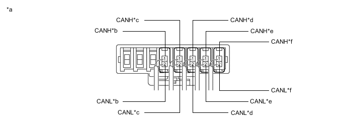
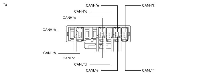
Connection diagram
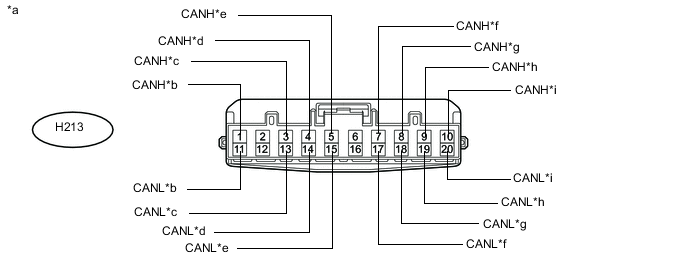
Text in Illustration *a Front view of wire harness connector
(to CAN Junction Connector LH1)
*b to Headlight Leveling ECU (Headlight Swivel ECU Assembly)
(for Bus 2)
*c to Engine Stop and Start ECU
(for 6AR- FSE)
(for Bus 2)
*d to Steering Sensor
(for Bus 2)
*e to Main Body ECU (Multiplex Network Body ECU)
(for Bus 2)
*f to Airbag Sensor Assembly
(for Bus 2)
*g to Combination Meter Assembly
(for Bus 2)
*h to CAN Junction Connector RH1
(for Bus 2)
*i to Power Steering ECU with Motor Assembly
(for Bus 2)
- - -
Check the connection diagram of the components which are connected to the CAN junction connector LH1.
Terminal No. (Symbol) Wiring Color Connected to H213-1 (CANH) Y Headlight leveling ECU (headlight swivel ECU assembly)
(for bus 2)
H213-11 (CANL) W H213-3 (CANH) BE Engine stop and start ECU*
(for bus 2)
H213-13 (CANL) W H213-4 (CANH) P Steering sensor
(for bus 2)
H213-14 (CANL) W H213-5 (CANH) V Main body ECU (multiplex network body ECU)
(for bus 2)
H213-15 (CANL) W H213-7 (CANH) L Airbag sensor assembly
(for bus 2)
H213-17 (CANL) W H213-8 (CANH) G Combination meter assembly
(for bus 2)
H213-18 (CANL) W H213-9 (CANH) R CAN junction connector RH1
(for bus 2)
H213-19 (CANL) W H213-10 (CANH) B Power steering ECU with motor assembly
(for bus 2)
H213-20 (CANL) W
-
*: for 6AR- FSE
-
-
-
-
CAN JUNCTION CONNECTOR RH1 (for LHD)
-
Check the CAN junction connector RH1.
Tech Tips
Connectors that connect to the CAN junction connector can be distinguished by the color of their CAN bus lines. When the connectors have been disconnected from the CAN junction connector, reconnecting the connectors to non-original positions on the CAN junction connector does not affect system performance. However, it is preferred to reconnect the connectors to their original positions to avoid negative effects on the wiring such as tension on the wire harnesses, and to make future maintenance easier.
-
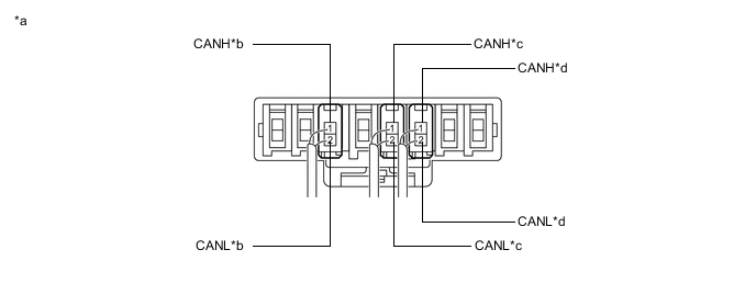
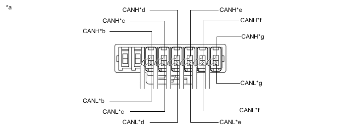
Connection diagram
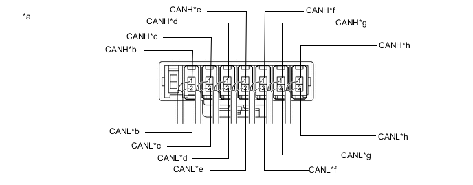
Text in Illustration *a Component with harness connected
(CAN Junction Connector RH1)
*b to Clearance Warning ECU Assembly
(for Bus 2)
*c to Certification ECU (Smart Key ECU Assembly)
(for Bus 2)
*d to Brake Actuator Assembly (Skid Control ECU)
(for Bus 2)
*e to Central Gateway ECU
(for Bus 2)
*f to Air Conditioning Amplifier Assembly
(for Bus 2)
*g to CAN Junction Connector LH1
(for Bus 2)
*h to ECM
(for Bus 2)
-
Check the connection diagram of the components which are connected to the CAN junction connector RH1.
Terminal No. (Symbol) Wiring Color Connected to H132-1 (CANH) P Clearance warning ECU assembly
(for bus 2)
H132-2 (CANL) W H127-1 (CANH) V Certification ECU (smart key ECU assembly)
(for bus 2)
H127-2 (CANL) W H126-1 (CANH) Y Brake actuator assembly (skid control ECU)
(for bus 2)
H126-2 (CANL) W H129-1 (CANH) BE Central gateway ECU
(for bus 2)
H129-2 (CANL) W H123-1 (CANH) G Air conditioning amplifier assembly
(for bus 2)
H123-2 (CANL) W H122-1 (CANH) R CAN junction connector LH1
(for bus 2)
H122-2 (CANL) W H125-1 (CANH) B ECM
(for bus 2)
H125-2 (CANL) W
-
-
-
CAN JUNCTION CONNECTOR LH2 (for LHD)
-
Check the CAN junction connector LH2.
Tech Tips
Connectors that connect to the CAN junction connector can be distinguished by the color of their CAN bus lines. When the connectors have been disconnected from the CAN junction connector, reconnecting the connectors to non-original positions on the CAN junction connector does not affect system performance. However, it is preferred to reconnect the connectors to their original positions to avoid negative effects on the wiring such as tension on the wire harnesses, and to make future maintenance easier.
-
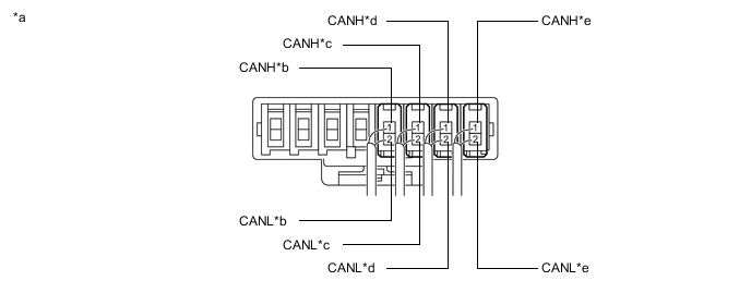
Connection diagram

Text in Illustration *a Component with harness connected
(CAN Junction connector LH2)
*b to Rear Television Camera Assembly
(w/ Parking Assist Monitor System without Parallel Parking Assist Function)
(for Sub Bus 1)
*c to Luggage Closer Motor Assembly
(w/ Power Trunk Lid System)
(for Sub Bus 1)
*d to Main Body ECU (Multiplex Network Body ECU)
(for Sub Bus 1)
*e to Multiplex Tilt and Telescopic ECU
(w/ Power Tilt and Power Telescopic Steering Column System)
(for Sub Bus 1)
*f to Outer Mirror Control ECU Assembly (for Driver Side)
(w/ Reverse Shift-linked Mirror)
(for Sub Bus 1)
*g to Front Power Seat Switch LH
(w/ Seat Position Memory System)
(for Sub Bus 1)
*h to CAN Junction Connector RH2
(for Sub Bus 1)
-
Check the connection diagram of the components which are connected to the CAN junction connector LH2.
Terminal No. (Symbol) Wiring Color Connected to H185-1 (CANH) P Rear television camera assembly*1
(for sub bus 1)
H185-2 (CANL) GR H135-1 (CANH) V Luggage closer motor assembly*2
(for sub bus 1)
H135-2 (CANL) GR H136-1 (CANH) Y Main body ECU (multiplex network body ECU)
(for sub bus 1)
H136-2 (CANL) GR H137-1 (CANH) L Multiplex tilt and telescopic ECU*3
(for sub bus 1)
H137-2 (CANL) GR H138-1 (CANH) G Outer mirror control ECU assembly (for driver side)*4
(for sub bus 1)
H138-2 (CANL) GR H140-1 (CANH) R Front power seat switch LH*5
(for sub bus 1)
H140-2 (CANL) GR H142-1 (CANH) B CAN junction connector RH2
(for sub bus 1)
H142-2 (CANL) GR
-
*1: w/ Parking Assist Monitor System without Parallel Parking Assist Function
-
*2: w/ Power Trunk Lid System
-
*3: w/ Power Tilt and Power Telescopic Steering Column System
-
*4: w/ Reverse Shift-linked Mirror
-
*5: w/ Seat Position Memory System
-
-
-
-
CAN JUNCTION CONNECTOR RH2 (for LHD)
-
Check the CAN junction connector RH2.
Tech Tips
Connectors that connect to the CAN junction connector can be distinguished by the color of their CAN bus lines. When the connectors have been disconnected from the CAN junction connector, reconnecting the connectors to non-original positions on the CAN junction connector does not affect system performance. However, it is preferred to reconnect the connectors to their original positions to avoid negative effects on the wiring such as tension on the wire harnesses, and to make future maintenance easier.
-
Connection diagram
Text in Illustration *a Component with harness connected
(CAN Junction Connector RH2)
*b to No. 1 CAN Junction Terminal
(for Sub Bus 1)
*c to Front Power Seat Switch RH
(w/ Seat Position Memory System)
(for Sub Bus 1)
*d to Outer Mirror Control ECU Assembly (for Front Passenger Side)
(w/ Reverse Shift-linked Mirror)
(for Sub Bus 1)
*e to CAN Junction Connector LH2
(for Sub Bus 1)
- - -
Check the connection diagram of the components which are connected to the CAN junction connector RH2.
Terminal No. (Symbol) Wiring Color Connected to H144-1 (CANH) L No. 1 CAN junction terminal
(for sub bus 1)
H144-2 (CANL) GR H141-1 (CANH) G Front power seat switch RH*1
(for sub bus 1)
H141-2 (CANL) GR H139-1 (CANH) R Outer mirror control ECU assembly (for front passenger side)*2
(for sub bus 1)
H139-2 (CANL) GR H143-1 (CANH) B CAN junction connector LH2
(for sub bus 1)
H143-2 (CANL) GR
-
*1: w/ Seat Position Memory System
-
*2: w/ Reverse Shift-linked Mirror
-
-
-
-
NO. 3 CAN JUNCTION CONNECTOR (for LHD)
-
Check the No. 3 CAN junction connector.
-
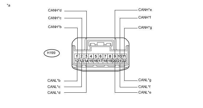
Connection diagram
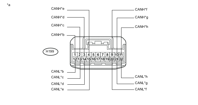
Text in Illustration *a Front view of wire harness connector
(to No. 3 CAN Junction Connector)
*b to Central Gateway ECU
(for Bus 3)
*c to Central Gateway ECU
(for Bus 3)
*d to Radio Receiver Assembly
(for Bus 3)
*e to Telematics Transceiver
(w/ Telematics Transceiver)
(for Bus 3)
*f to Forward Recognition Camera
(w/ Lexus Safety System +)
(for Sub Bus 13)
*g to Driving Support ECU Assembly
(w/ Lexus Safety System +)
(for Sub Bus 13)
*h to Millimeter Wave Radar Sensor Assembly
(w/ Lexus Safety System +)
(for Sub Bus 13)
-
-
Check the connection diagram of the components which are connected to the No. 3 CAN junction connector.
Terminal No. (Symbol) Wiring Color Connected to H199-1 (CANH) W Central gateway ECU
(for bus 3)
H199-12 (CANL) B H199-2 (CANH) GR Central gateway ECU
(for bus 3)
H199-13 (CANL) B H199-3 (CANH) LG Radio receiver assembly
(for bus 3)
H199-14 (CANL) B H199-4 (CANH) R Telematics transceiver*1
(for bus 3)
H199-15 (CANL) B H199-9 (CANH) B Forward recognition camera*2
(for sub bus 13)
H199-20 (CANL) W H199-10 (CANH) P Driving support ECU assembly*2
(for sub bus 13)
H199-21 (CANL) GR H199-11 (CANH) R Millimeter wave radar sensor assembly*2
(for sub bus 13)
H199-22 (CANL) LG *1: w/ Telematics Transceiver
*2: w/ Lexus Safety System +
-
-
NO. 4 CAN JUNCTION CONNECTOR (for LHD)
-
Check the No. 4 CAN junction connector.
Tech Tips
Connectors that connect to the CAN junction connector can be distinguished by the color of their CAN bus lines. When the connectors have been disconnected from the CAN junction connector, reconnecting the connectors to non-original positions on the CAN junction connector does not affect system performance. However, it is preferred to reconnect the connectors to their original positions to avoid negative effects on the wiring such as tension on the wire harnesses, and to make future maintenance easier.
-
Connection diagram
Text in Illustration *a Component with harness connected
(No. 4 CAN Junction Connector)
*b to Millimeter Wave Radar Sensor Assembly
(w/ Lexus Safety System +)
(for Bus 5)
*c to Central Gateway ECU
(for Bus 5)
*d to No. 5 CAN Junction Connector
(for Bus 5)
*e to Forward Recognition Camera
(w/ Lexus Safety System +)
(for Bus 5)
*f to Driving Support ECU Assembly
(w/ Lexus Safety System +)
(for Bus 5)
-
-
Check the connection diagram of the components which are connected to the No. 4 CAN junction connector.
Terminal No. (Symbol) Wiring Color Connected to H205-1 (CANH) Y Millimeter wave radar sensor assembly*
(for bus 5)
H205-2 (CANL) LG H202-1 (CANH) L Central gateway ECU
(for bus 5)
H202-2 (CANL) LG H203-1 (CANH) G No. 5 CAN junction connector
(for bus 5)
H203-2 (CANL) LG H204-1 (CANH) R Forward recognition camera*
(for bus 5)
H204-2 (CANL) LG H206-1 (CANH) B Driving support ECU assembly*
(for bus 5)
H206-2 (CANL) LG *: w/ Lexus Safety System +
-
-
NO. 5 CAN JUNCTION CONNECTOR (for LHD)
-
Check the No. 5 CAN junction connector.
Tech Tips
Connectors that connect to the CAN junction connector can be distinguished by the color of their CAN bus lines. When the connectors have been disconnected from the CAN junction connector, reconnecting the connectors to non-original positions on the CAN junction connector does not affect system performance. However, it is preferred to reconnect the connectors to their original positions to avoid negative effects on the wiring such as tension on the wire harnesses, and to make future maintenance easier.
-
Connection diagram
Text in Illustration *a Component with harness connected
(No. 5 CAN Junction Connector)
*b to Blind Spot Monitor Sensor LH
(w/ Blind Spot Monitor System)
(for Bus 5)
*c to No. 2 CAN Junction Terminal
(for Bus 5)
*d to No. 4 CAN Junction Connector
(for Bus 5)
-
Check the connection diagram of the components which are connected to the No. 5 CAN junction connector.
Terminal No. (Symbol) Wiring Color Connected to U26-1 (CANH) V Blind spot monitor sensor LH*
(for bus 5)
U26-2 (CANL) LG U28-1 (CANH) Y No. 2 CAN junction terminal
(for bus 5)
U28-2 (CANL) LG U25-1 (CANH) G No. 4 CAN junction connector
(for bus 5)
U25-2 (CANL) LG *: w/ Blind Spot Monitor System
-
-
-
CAN JUNCTION CONNECTOR LH1 (for RHD)
-
Check the CAN junction connector LH1.
Tech Tips
Connectors that connect to the CAN junction connector can be distinguished by the color of their CAN bus lines. When the connectors have been disconnected from the CAN junction connector, reconnecting the connectors to non-original positions on the CAN junction connector does not affect system performance. However, it is preferred to reconnect the connectors to their original positions to avoid negative effects on the wiring such as tension on the wire harnesses, and to make future maintenance easier.
-
Connection diagram
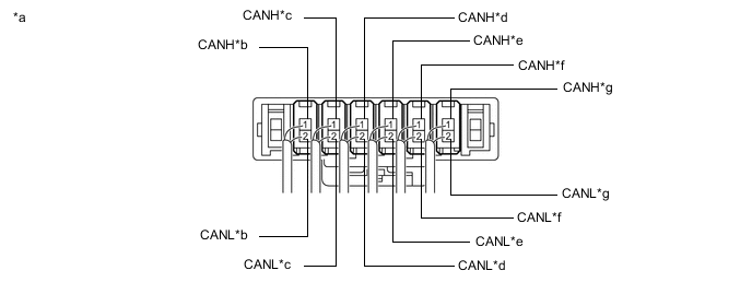
Text in Illustration *a Component with harness connected
(CAN Junction Connector LH1)
*b to Power Steering ECU with Motor Assembly
(for Bus 2)
*c to Main Body ECU (Multiplex Network Body ECU)
(for Bus 2)
*d to Airbag Sensor Assembly
(for Bus 2)
*e to ECM
(for Bus 2)
*f to Air Conditioning Amplifier Assembly
(for Bus 2)
*g to CAN Junction Connector RH1
(for Bus 2)
- - -
Check the connection diagram of the components which are connected to the CAN junction connector LH1.
Terminal No. (Symbol) Wiring Color Connected to H167-1 (CANH) P Power steering ECU with motor assembly
(for bus 2)
H167-2 (CANL) W H118-1 (CANH) V Main body ECU (multiplex network body ECU)
(for bus 2)
H118-2 (CANL) W H211-1 (CANH) Y Airbag sensor assembly
(for bus 2)
H211-2 (CANL) W H125-1 (CANH) L ECM
(for bus 2)
H125-2 (CANL) W H123-1 (CANH) G Air conditioning amplifier assembly
(for bus 2)
H123-2 (CANL) W H116-1 (CANH) R CAN junction connector RH1
(for bus 2)
H116-2 (CANL) W
-
-
-
CAN JUNCTION CONNECTOR RH1 (for RHD)
-
Check the CAN junction connector RH1.
Tech Tips
Connectors that connect to the CAN junction connector can be distinguished by the color of their CAN bus lines. When the connectors have been disconnected from the CAN junction connector, reconnecting the connectors to non-original positions on the CAN junction connector does not affect system performance. However, it is preferred to reconnect the connectors to their original positions to avoid negative effects on the wiring such as tension on the wire harnesses, and to make future maintenance easier.
-
Connection diagram
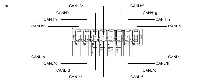
Text in Illustration *a Component with harness connected
(CAN Junction Connector RH1)
*b to Steering Sensor
(for Bus 2)
*c to Clearance Warning ECU Assembly
(for Bus 2)
*d to Certification ECU (Smart Key ECU Assembly)
(for Bus 2)
*e to Central Gateway ECU
(for Bus 2)
*f to Headlight Leveling ECU (Headlight Swivel ECU Assembly)
(for Bus 2)
*g to Combination Meter Assembly
(for Bus 2)
*h to CAN Junction Connector LH1
(for Bus 2)
*i to Brake Actuator Assembly (Skid Control ECU)
(for Bus 2)
- - -
Check the connection diagram of the components which are connected to the CAN junction connector RH1.
Terminal No. (Symbol) Wiring Color Connected to H120-1 (CANH) BE Steering sensor
(for bus 2)
H120-2 (CANL) W H132-1 (CANH) P Clearance warning ECU assembly
(for bus 2)
H132-2 (CANL) W H127-1 (CANH) V Certification ECU (smart key ECU assembly)
(for bus 2)
H127-2 (CANL) W H129-1 (CANH) Y Central gateway ECU
(for bus 2)
H129-2 (CANL) W H214-1 (CANH) L Headlight leveling ECU (headlight swivel ECU assembly)
(for bus 2)
H214-2 (CANL) W H117-1 (CANH) G Combination meter assembly
(for bus 2)
H117-2 (CANL) W H122-1 (CANH) R CAN junction connector LH1
(for bus 2)
H122-2 (CANL) W H126-1 (CANH) B Brake actuator assembly (skid control ECU)
(for bus 2)
H126-2 (CANL) W
-
-
-
CAN JUNCTION CONNECTOR LH2 (for RHD)
-
Check the CAN junction connector LH2.
Tech Tips
Connectors that connect to the CAN junction connector can be distinguished by the color of their CAN bus lines. When the connectors have been disconnected from the CAN junction connector, reconnecting the connectors to non-original positions on the CAN junction connector does not affect system performance. However, it is preferred to reconnect the connectors to their original positions to avoid negative effects on the wiring such as tension on the wire harnesses, and to make future maintenance easier.
-
Connection diagram
Text in Illustration *a Component with harness connected
(CAN Junction Connector LH2)
*b to Rear Television Camera Assembly
(w/ Parking Assist Monitor System without Parallel Parking Assist Function)
(for Sub Bus 1)
*c to Main Body ECU (Multiplex Network Body ECU)
(for Sub Bus 1)
*d to Outer Mirror Control ECU Assembly (for Front Passenger Side)
(for Sub Bus 1)
*e to Front Power Seat Switch LH
(w/ Seat Position Memory System (for Front Passenger Side))
(for Sub Bus 1)
*f to CAN Junction Connector RH2
(for Sub Bus 1)
-
Check the connection diagram of the components which are connected to the CAN junction connector LH2.
Terminal No. (Symbol) Wiring Color Connected to H185-1 (CANH) P Rear television camera assembly*1
(for sub bus 1)
H185-2 (CANL) GR H136-1 (CANH) L Main body ECU (multiplex network body ECU)
(for sub bus 1)
H136-2 (CANL) GR H138-1 (CANH) G Outer mirror control ECU assembly (for front passenger side)
(for sub bus 1)
H138-2 (CANL) GR H140-1 (CANH) R Front power seat switch LH*2
(for sub bus 1)
H140-2 (CANL) GR H142-1 (CANH) B CAN junction connector RH2
(for sub bus 1)
H142-2 (CANL) GR
-
*1: w/ Parking Assist Monitor System without Parallel Parking Assist Function
-
*2: w/ Seat Position Memory System (for Front Passenger Side)
-
-
-
-
CAN JUNCTION CONNECTOR RH2 (for RHD)
-
Check the CAN junction connector RH2.
Tech Tips
Connectors that connect to the CAN junction connector can be distinguished by the color of their CAN bus lines. When the connectors have been disconnected from the CAN junction connector, reconnecting the connectors to non-original positions on the CAN junction connector does not affect system performance. However, it is preferred to reconnect the connectors to their original positions to avoid negative effects on the wiring such as tension on the wire harnesses, and to make future maintenance easier.
-
Connection diagram
Text in Illustration *a Component with harness connected
(CAN Junction Connector RH2)
*b to No. 1 CAN Junction Terminal
(for Sub Bus 1)
*c Luggage Closer Motor Assembly
(w/ Power Trunk Lid System)
(for Sub Bus 1)
*d to Multiplex Tilt and Telescopic ECU
(w/ Power Tilt and Power Telescopic Steering Column System)
(for Sub Bus 1)
*e to Front Power Seat Switch RH
(for Sub Bus 1)
*f to Outer Mirror Control ECU Assembly (for Driver Side)
(for Sub Bus 1)
*g to CAN Junction Connector LH2
(for Sub Bus 1)
- - -
Check the connection diagram of the components which are connected to the CAN junction connector RH2.
Terminal No. (Symbol) Wiring Color Connected to H144-1 (CANH) V No. 1 CAN junction terminal
(for sub bus 1)
H144-2 (CANL) GR H135-1 (CANH) V Luggage closer motor assembly*1
(for sub bus 1)
H135-2 (CANL) GR H137-1 (CANH) L Multiplex tilt and telescopic ECU*2
(for sub bus 1)
H137-2 (CANL) GR H141-1 (CANH) G Front power seat switch RH
(for sub bus 1)
H141-2 (CANL) GR H139-1 (CANH) R Outer mirror control ECU assembly (for driver side)
(for sub bus 1)
H139-2 (CANL) GR H143-1 (CANH) B CAN junction connector LH2
(for sub bus 1)
H143-2 (CANL) GR
-
*1: w/ Power Trunk Lid System
-
*2: w/ Power Tilt and Power Telescopic Steering Column System
-
-
-
-
NO. 3 CAN JUNCTION CONNECTOR (for RHD)
-
Check the No. 3 CAN junction connector.
-
Connection diagram
Text in Illustration *a Front view of wire harness connector
(to No. 3 CAN Junction Connector)
*b to Central Gateway ECU
(for Bus 3)
*c to Central Gateway ECU
(for Bus 3)
*d to Radio Receiver Assembly
(for Bus 3)
*e to Forward Recognition Camera
(w/ Lexus Safety System +)
(for Sub Bus 13)
*f to Driving Support ECU Assembly
(w/ Lexus Safety System +)
(for Sub Bus 13)
*g to Millimeter Wave Radar Sensor Assembly
(w/ Lexus Safety System +)
(for Sub Bus 13)
- -
-
-
Check the connection diagram of the components which are connected to the No. 3 CAN junction connector.
Terminal No. (Symbol) Wiring Color Connected to H199-1 (CANH) W Central gateway ECU
(for bus 3)
H199-12 (CANL) B H199-2 (CANH) GR Central gateway ECU
(for bus 3)
H199-13 (CANL) B H199-3 (CANH) LG Radio receiver assembly
(for bus 3)
H199-14 (CANL) B H199-9 (CANH) B Forward recognition camera*
(for sub bus 13)
H199-20 (CANL) W H199-10 (CANH) P Driving support ECU assembly*
(for sub bus 13)
H199-21 (CANL) GR H199-11 (CANH) R Millimeter wave radar sensor assembly*
(for sub bus 13)
H199-22 (CANL) LG *: w/ Lexus Safety System +
-
-
NO. 4 CAN JUNCTION CONNECTOR (for RHD)
-
Check the No. 4 CAN junction connector.
Tech Tips
Connectors that connect to the CAN junction connector can be distinguished by the color of their CAN bus lines. When the connectors have been disconnected from the CAN junction connector, reconnecting the connectors to non-original positions on the CAN junction connector does not affect system performance. However, it is preferred to reconnect the connectors to their original positions to avoid negative effects on the wiring such as tension on the wire harnesses, and to make future maintenance easier.
-
Connection diagram

Text in Illustration *a Component with harness connected
(No. 4 CAN Junction Connector)
*b to Millimeter Wave Radar Sensor Assembly
(w/ Lexus Safety System +)
(for Bus 5)
*c to Central Gateway ECU
(for Bus 5)
*d to No. 5 CAN Junction Connector
(for Bus 5)
*e to Forward Recognition Camera
(w/ Lexus Safety System +)
(for Bus 5)
*f to Driving Support ECU Assembly
(w/ Lexus Safety System +)
(for Bus 5)
-
-
Check the connection diagram of the components which are connected to the No. 4 CAN junction connector.
Terminal No. (Symbol) Wiring Color Connected to H205-1 (CANH) Y Millimeter wave radar sensor assembly*
(for bus 5)
H205-2 (CANL) LG H202-1 (CANH) L Central gateway ECU
(for bus 5)
H202-2 (CANL) LG H203-1 (CANH) G No. 5 CAN junction connector
(for bus 5)
H203-2 (CANL) LG H204-1 (CANH) R Forward recognition camera*
(for bus 5)
H204-2 (CANL) LG H206-1 (CANH) B Driving support ECU assembly*
(for bus 5)
H206-2 (CANL) LG *: w/ Lexus Safety System +
-
-
NO. 5 CAN JUNCTION CONNECTOR (for RHD)
-
Check the No. 5 CAN junction connector.
Tech Tips
Connectors that connect to the CAN junction connector can be distinguished by the color of their CAN bus lines. When the connectors have been disconnected from the CAN junction connector, reconnecting the connectors to non-original positions on the CAN junction connector does not affect system performance. However, it is preferred to reconnect the connectors to their original positions to avoid negative effects on the wiring such as tension on the wire harnesses, and to make future maintenance easier.
-
Connection diagram

Text in Illustration *a Component with harness connected
(No. 5 CAN Junction Connector)
*b to Blind Spot Monitor Sensor LH
(w/ Blind Spot Monitor System)
(for Bus 5)
*c to No. 2 CAN Junction Terminal
(for Bus 5)
*d to No. 4 CAN Junction Connector
(for Bus 5)
-
Check the connection diagram of the components which are connected to the No. 5 CAN junction connector.
Terminal No. (Symbol) Wiring Color Connected to U26-1 (CANH) V Blind spot monitor sensor LH*
(for bus 5)
U26-2 (CANL) LG U28-1 (CANH) Y No. 2 CAN junction terminal
(for bus 5)
U28-2 (CANL) LG U25-1 (CANH) G No. 4 CAN junction connector
(for bus 5)
U25-2 (CANL) LG *: w/ Blind Spot Monitor System
-
-
-
NO. 1 CAN JUNCTION TERMINAL
-
Check the No. 1 CAN junction terminal.
-
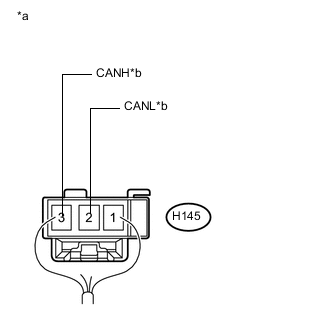
Text in Illustration *a Rear view of wire harness connector
(to No. 1 CAN Junction Terminal)
*b to CAN Junction Connector RH2
(for Sub Bus 1)
Connection diagram
-
Check the connection diagram of the components which are connected to the No. 1 CAN junction terminal.
Terminal No. (Symbol) Wiring Color Connected to H145-3 (CANH) L*1
V*2
CAN junction connector RH2
(for sub bus 1)
H145-2 (CANL) GR
-
*1: for LHD
-
*2: for RHD
-
-
-
-
NO. 2 CAN JUNCTION TERMINAL
-
Check the No. 2 CAN junction terminal.
-
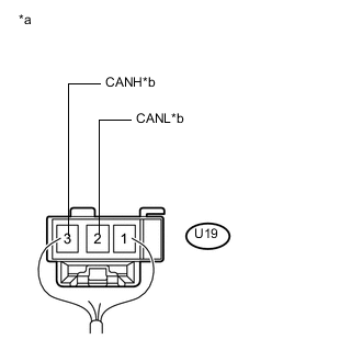
Text in Illustration *a Rear view of wire harness connector
(to No. 2 CAN Junction Terminal)
*b to No. 5 CAN Junction Connector
(for Bus 5)
Connection diagram
-
Check the connection diagram of the components which are connected to the No. 2 CAN junction terminal.
Terminal No. (Symbol) Wiring Color Connected to U19-3 (CANH) Y No. 5 CAN junction connector
(for bus 5)
U19-2 (CANL) LG
-
-
-
DLC3
-
Disconnect the cable from the negative (-) battery terminal.
-
Measure the resistance according to the value(s) in the table below.
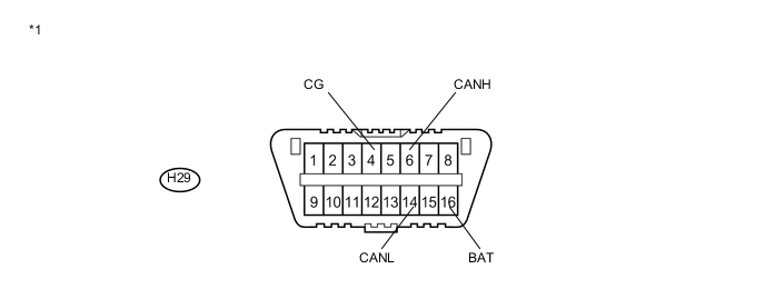
Text in Illustration *1 DLC3 - -
-
-
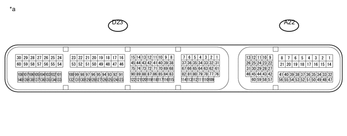
ECM (for 2GR-FE)
Text in Illustration *a Component without harness connected
(ECM)
- -
-
Disconnect the cable from the negative (-) battery terminal.
-
Disconnect the A22 and D23 ECM connectors.
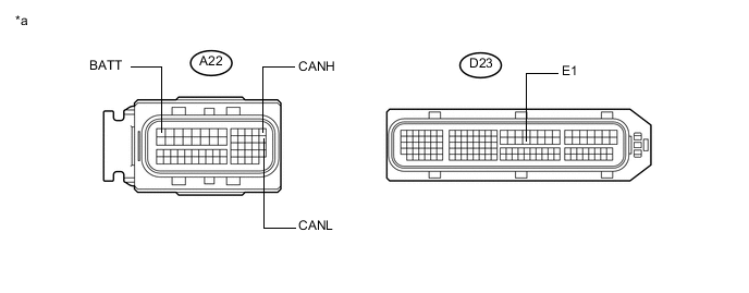
Text in Illustration *a Front view of wire harness connector
(to ECM)
- - -
Measure the resistance according to the value(s) in the table below.
-
-
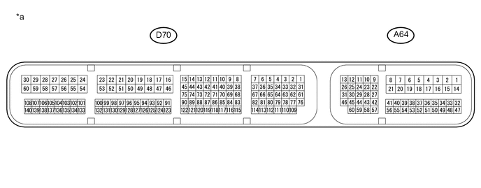
ECM (for 2AR-FE)
Text in Illustration *a Component without harness connected
(ECM)
- -
-
Disconnect the cable from the negative (-) battery terminal.
-
Disconnect the A64 and D70 ECM connectors.
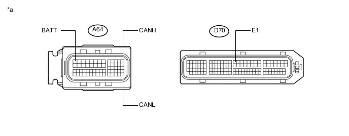
Text in Illustration *a Front view of wire harness connector
(to ECM)
- - -
Measure the resistance according to the value(s) in the table below.
-
-
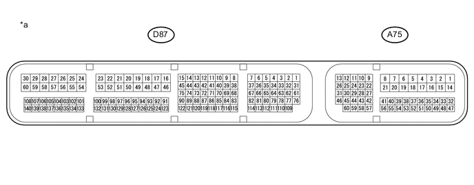
ECM (for 6AR-FSE)
Text in Illustration *a Component without harness connected
(ECM)
- -
-
Disconnect the cable from the negative (-) battery terminal.
-
Disconnect the A75 and D87 ECM connectors.
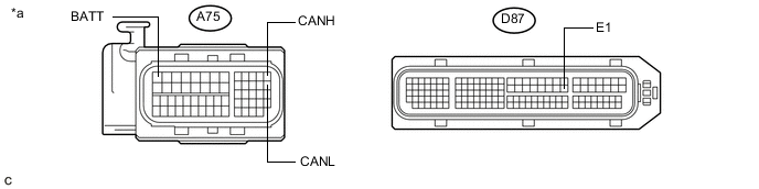
Text in Illustration *a Front view of wire harness connector
(to ECM)
- - -
Measure the resistance according to the value(s) in the table below.
-
-
COMBINATION METER ASSEMBLY
Text in Illustration *a Component without harness connected
(Combination Meter Assembly)
- -
-
Disconnect the cable from the negative (-) battery terminal.
-
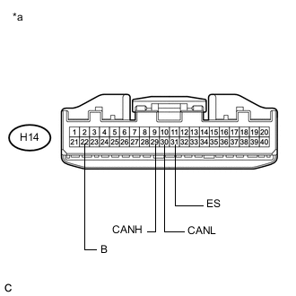
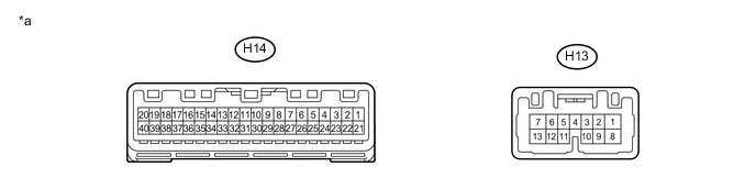
Text in Illustration *a Front view of wire harness connector
(to Combination Meter Assembly)
Disconnect the H14 combination meter assembly connector.
-
Measure the resistance according to the value(s) in the table below.
-
-
INSTRUMENT PANEL JUNCTION BLOCK ASSEMBLY AND MAIN BODY ECU (MULTIPLEX NETWORK BODY ECU)
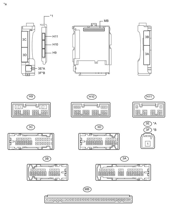
Text in Illustration *A for LHD *B for RHD *1 Main Body ECU (Multiplex Network Body ECU) - - *a Component without harness connected
(Instrument Panel Junction Block Assembly and Main Body ECU (Multiplex Network Body ECU))
- -
-
Disconnect the cable from the negative (-) battery terminal.
-
Disconnect the H9 and H10 main body ECU (multiplex network body ECU) connectors.
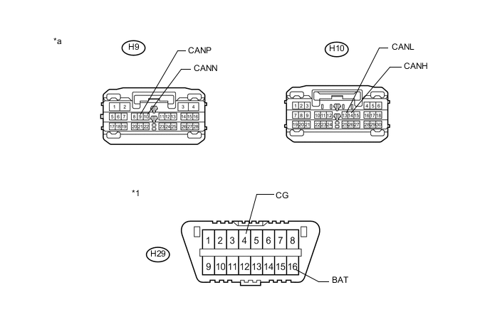
Text in Illustration *1 DLC3 - - *a Front view of wire harness connector
(to Main Body ECU (Multiplex Network Body ECU))
- - -
Measure the resistance according to the value(s) in the table below.
-
*1: for LHD
-
*2: for RHD
-
-
-
BRAKE ACTUATOR ASSEMBLY (SKID CONTROL ECU)
Text in Illustration *a Component without harness connected
(Brake Actuator Assembly (Skid Control ECU))
- -
-
Disconnect the cable from the negative (-) battery terminal.
-
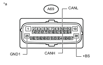
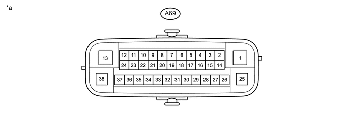
Text in Illustration *a Front view of wire harness connector
(to Brake Actuator Assembly (Skid Control ECU))
Disconnect the A69 brake actuator assembly (skid control ECU) connector.
-
Measure the resistance according to the value(s) in the table below.
-
-
STEERING SENSOR
-
Disconnect the cable from the negative (-) battery terminal.
-
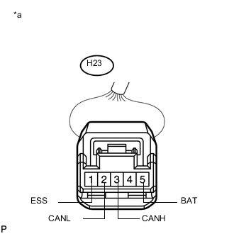
Text in Illustration *a Front view of wire harness connector
(to Steering Sensor)
Disconnect the H23 steering sensor connector.
-
Measure the resistance according to the value(s) in the table below.
-
*1: for LHD
-
*2: for RHD
-
-
-
POWER STEERING ECU WITH MOTOR ASSEMBLY
Text in Illustration *a Component without harness connected
(Power Steering ECU with Motor Assembly)
- -
-
Disconnect the cable from the negative (-) battery terminal.
-
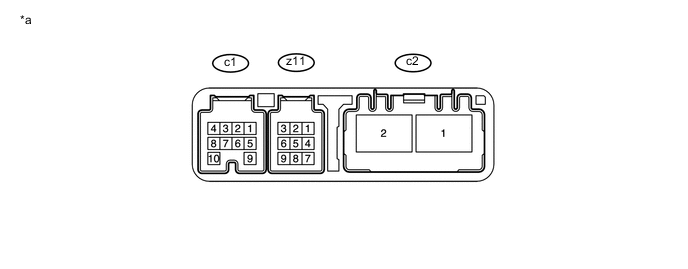
Disconnect the c1 and c2 power steering ECU with motor assembly connectors.
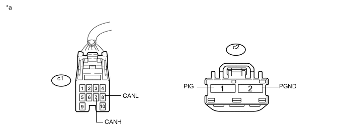
Text in Illustration *a Front view of wire harness connector
(to Power Steering ECU with Motor Assembly)
- - -
Measure the resistance according to the value(s) in the table below.
-
-
AIRBAG SENSOR ASSEMBLY
-
Disconnect the cable from the negative (-) battery terminal.
-
Disconnect the H36 airbag sensor assembly connector.
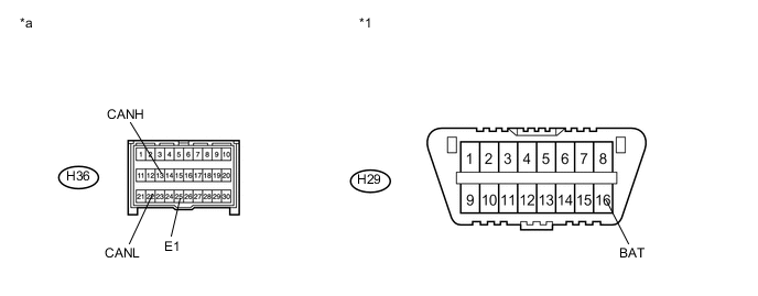
Text in Illustration *1 DLC3 - - *a Front view of wire harness connector
(to Airbag Sensor Assembly)
- - -
Measure the resistance according to the value(s) in the table below.
-
*1: for LHD
-
*2: for RHD
-
-
-
CERTIFICATION ECU (SMART KEY ECU ASSEMBLY)

Text in Illustration *a Component without harness connected
(Certification ECU (Smart Key ECU Assembly))
- -
-
Disconnect the cable from the negative (-) battery terminal.
-
Disconnect the A36 and H56 certification ECU (smart key ECU assembly) connectors.
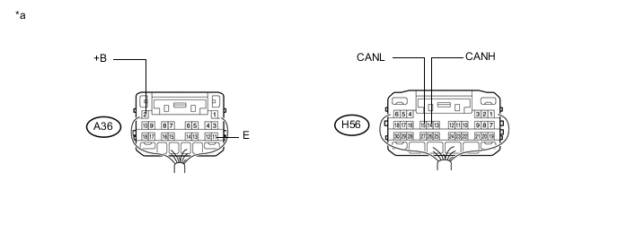
Text in Illustration *a Rear view of wire harness connector
(to Certification ECU (Smart Key ECU Assembly))
- - -
Measure the resistance according to the value(s) in the table below.
-
-
RADIO RECEIVER ASSEMBLY (for Navigation Receiver Type)
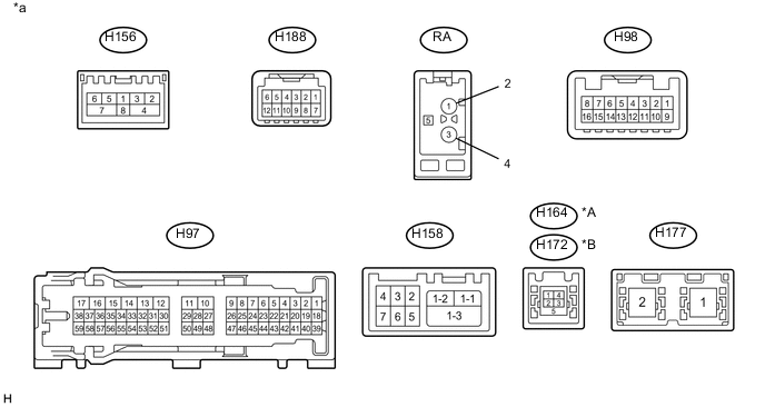
Text in Illustration *A for LHD *B for RHD *a Component without harness connected
(Radio Receiver Assembly)
- -
-
Disconnect the cable from the negative (-) battery terminal.
-
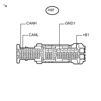
Text in Illustration *a Front view of wire harness connector
(to Radio Receiver Assembly)
Disconnect the H97 radio receiver assembly connector.
-
Measure the resistance according to the value(s) in the table below.
-
*1: for 6AR-FSE
-
*2: except 6AR-FSE
-
-
-
RADIO RECEIVER ASSEMBLY (for Radio and Display Type)
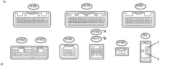
Text in Illustration *A for LHD *B for RHD *a Component without harness connected
(Radio Receiver Assembly)
- -
-
Disconnect the cable from the negative (-) battery terminal.
-
Disconnect the H179 and H182 radio receiver assembly connectors.
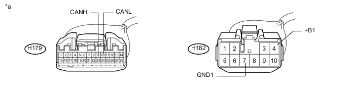
Text in Illustration *a Front view of wire harness connector
(to Radio Receiver Assembly)
- - -
Measure the resistance according to the value(s) in the table below.
-
*1: for 6AR-FSE
-
*2: except 6AR-FSE
-
-
-
AIR CONDITIONING AMPLIFIER ASSEMBLY
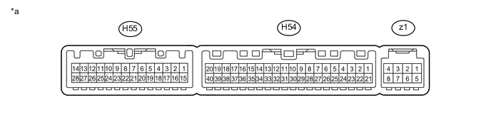
Text in Illustration *a Component without harness connected
(Air Conditioning Amplifier Assembly)
- -
-
Disconnect the cable from the negative (-) battery terminal.
-
Disconnect the H54 air conditioning amplifier assembly connector.
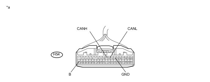
Text in Illustration *a Front view of wire harness connector
(to Air Conditioning Amplifier Assembly)
- - -
Measure the resistance according to the value(s) in the table below.
-
-
CLEARANCE WARNING ECU ASSEMBLY
-
Disconnect the cable from the negative (-) battery terminal.
-
Disconnect the H61 clearance warning ECU assembly connector.
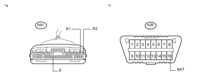
Text in Illustration *1 DLC3 - - *a Front view of wire harness connector
(to Clearance Warning ECU Assembly)
- - -
Measure the resistance according to the value(s) in the table below.
-
-
CENTRAL GATEWAY ECU
Text in Illustration *a Component without harness connected
(Central Gateway ECU)
- -
-
Disconnect the cable from the negative (-) battery terminal.
-
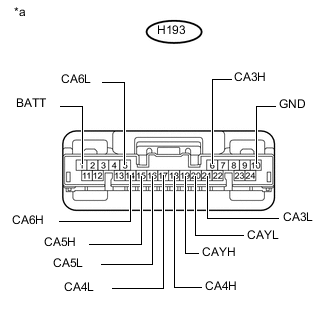
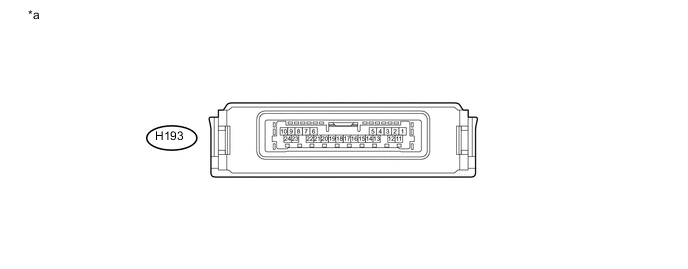
Text in Illustration *a Front view of wire harness connector
(to Central Gateway ECU)
Disconnect the H193 central gateway ECU connector.
-
Measure the resistance according to the value(s) in the table below.
-
*1: for LHD
-
*2: for RHD
-
-
-
OUTER MIRROR CONTROL ECU ASSEMBLY (for Driver Side with Reverse Shift-linked Mirror)

Text in Illustration *A for LHD *B for RHD *a Component without harness connected
(Outer Mirror Control ECU Assembly (for Driver Side))
- -
-
Disconnect the cable from the negative (-) battery terminal.
-
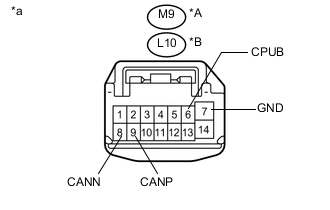
Text in Illustration *A for LHD *B for RHD *a Front view of wire harness connector
(to Outer Mirror Control ECU Assembly (for Driver Side))
Disconnect the M9 or L10 outer mirror control ECU assembly (for driver side) connector.
-
Measure the resistance according to the value(s) in the table below.
-
-
OUTER MIRROR CONTROL ECU ASSEMBLY (for Front Passenger Side with Reverse Shift-linked Mirror)

Text in Illustration *A for LHD *B for RHD *a Component without harness connected
(Outer Mirror Control ECU Assembly (for Front Passenger Side))
- -
-
Disconnect the cable from the negative (-) battery terminal.
-
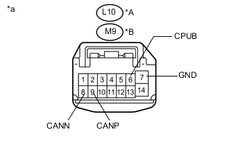
Text in Illustration *A for LHD *B for RHD *a Front view of wire harness connector
(to Outer Mirror Control ECU Assembly (for Front Passenger Side))
Disconnect the M9 or L10 outer mirror control ECU assembly (for front passenger side) connector.
-
Measure the resistance according to the value(s) in the table below.
-
-
FRONT POWER SEAT SWITCH LH (w/ Seat Position Memory System)

Text in Illustration *a Component without harness connected
(Front Power Seat Switch LH)
- -
-
Disconnect the cable from the negative (-) battery terminal.
-
Disconnect the X9 and X10 front power seat switch LH connectors.
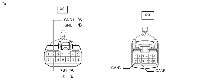
*A for LHD *B for RHD *a Front view of wire harness connector
(to Front Power Seat Switch LH)
- - -
Measure the resistance according to the value(s) in the table below.
-
*1: for LHD
-
*2: for RHD
-
-
-
FRONT POWER SEAT SWITCH RH (w/ Seat Position Memory System)

Text in Illustration *a Component without harness connected
(Front Power Seat Switch RH)
- -
-
Disconnect the cable from the negative (-) battery terminal.
-
Disconnect the W9 and W10 front power seat switch RH connectors.
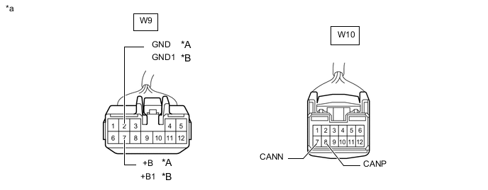
*A for LHD *B for RHD *a Front view of wire harness connector
(to Front Power Seat Switch RH)
- - -
Measure the resistance according to the value(s) in the table below.
-
*1: for LHD
-
*2: for RHD
-
-
-
MULTIPLEX TILT AND TELESCOPIC ECU (w/ Power Tilt and Power Telescopic Steering Column System)

Text in Illustration *a Component without harness connected
(Multiplex Tilt and Telescopic ECU)
- -
-
Disconnect the cable from the negative (-) battery terminal.
-
Disconnect the H12 multiplex tilt and telescopic ECU connector.
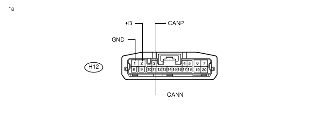
Text in Illustration *a Front view of wire harness connector
(to Multiplex Tilt and Telescopic ECU)
- - -
Measure the resistance according to the value(s) in the table below.
-
-
LUGGAGE CLOSER MOTOR ASSEMBLY (w/ Power Trunk Lid System)

Text in Illustration *a Component without harness connected
(Luggage Closer Motor Assembly)
- -
-
Disconnect the cable from the negative (-) battery terminal.
-
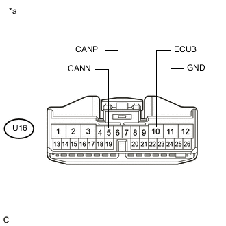
Text in Illustration *a Front view of wire harness connector
(to Luggage Closer Motor Assembly)
Disconnect the U16 luggage closer motor assembly connector.
-
Measure the resistance according to the value(s) in the table below.
-
-
BLIND SPOT MONITOR SENSOR LH (w/ Blind Spot Monitor System)

Text in Illustration *a Component without harness connected
(Blind Spot Monitor Sensor LH)
- -
-
Disconnect the cable from the negative (-) battery terminal.
-
Disconnect the U8 blind spot monitor sensor LH connector.
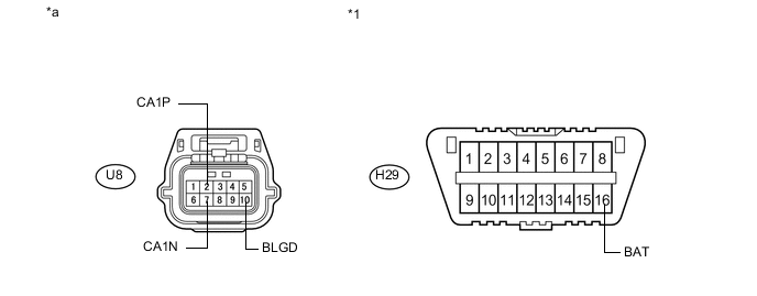
Text in Illustration *1 DLC3 - - *a Front view of wire harness connector
(to Blind Spot Monitor Sensor LH)
- - -
Measure the resistance according to the value(s) in the table below.
-
-
DRIVING SUPPORT ECU ASSEMBLY (w/ Lexus Safety System +)
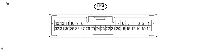
Text in Illustration *a Component without harness connected
(Driving Support ECU assembly)
- -
-
Disconnect the cable from the negative (-) battery terminal.
-
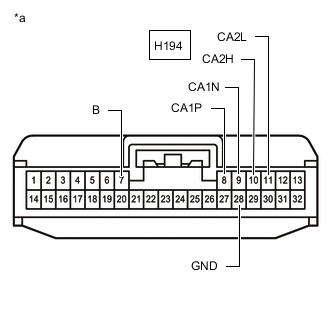
*a Front view of wire harness connector
(to Driving Support ECU Assembly)
Disconnect the H194 driving support ECU assembly connector.
-
Measure the resistance according to the value(s) in the table below.
-
-
FORWARD RECOGNITION CAMERA (w/ Lexus Safety System +)

Text in Illustration *a Component without harness connected
(Forward Recognition Camera)
- -
-
Disconnect the cable from the negative (-) battery terminal.
-
Disconnect the T12 forward recognition camera connector.
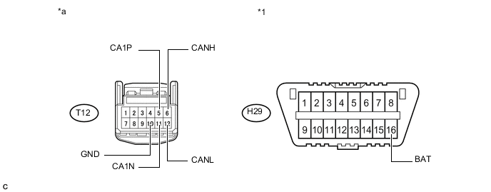
Text in Illustration *1 DLC3 - - *a Front view of wire harness connector
(to Forward Recognition Camera)
- - -
Measure the resistance according to the value(s) in the table below.
-
-
MILLIMETER WAVE RADAR SENSOR ASSEMBLY (w/ Lexus Safety System +)

Text in Illustration *a Component without harness connected
(Millimeter Wave Radar Sensor Assembly)
- -
-
Disconnect the cable from the negative (-) battery terminal.
-
Disconnect the A74 millimeter wave radar sensor assembly connector.
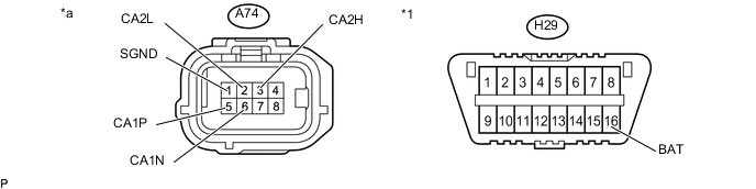
Text in Illustration *1 DLC3 - - *a Front view of wire harness connector
(to Millimeter Wave Radar Sensor Assembly)
- - -
Measure the resistance according to the value(s) in the table below.
-
-
TELEMATICS TRANSCEIVER (w/ Telematics Transceiver for G-BOOK)
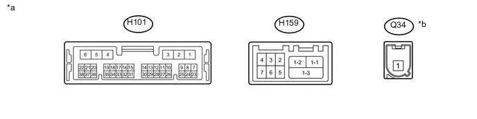
Text in Illustration *a Component without harness connected
(Telematics Transceiver)
*b to Telephone Antenna
-
Disconnect the cable from the negative (-) battery terminal.
-
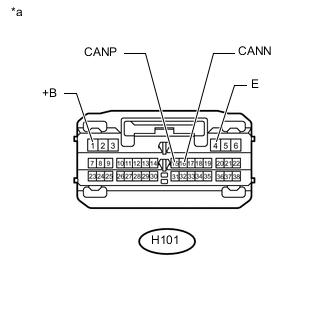
Text in Illustration *a Front view of wire harness connector
(to Telematics Transceiver)
Disconnect the H101 telematics transceiver connector.
-
Measure the resistance according to the value(s) in the table below.
-
-
TELEMATICS TRANSCEIVER (w/ Telematics Transceiver except G-BOOK)
-
Disconnect the cable from the negative (-) battery terminal.
-
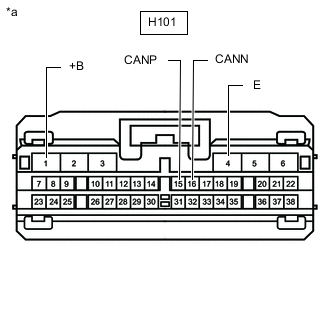
*a Front view of wire harness connector
(to Telematics Transceiver)
Disconnect the H101 telematics transceiver connector.
-
Measure the resistance according to the value(s) in the table below.
-
-
REAR TELEVISION CAMERA ASSEMBLY (w/ Parking Assist Monitor System without Parallel Parking Assist Function)
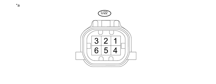
Text in Illustration *a Component without harness connected
(Rear Television Camera Assembly)
- -
-
Disconnect the cable from the negative (-) battery terminal.
-
Disconnect the U22 rear television camera assembly connector.
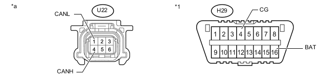
Text in Illustration *1 DLC3 - - *a Front view of wire harness connector
(to Rear Television Camera Assembly)
- - -
Measure the resistance according to the value(s) in the table below.
-
-
ENGINE STOP AND START ECU (for 6AR-FSE)
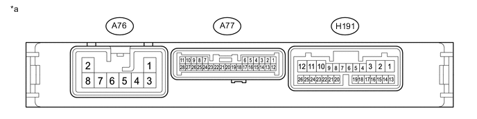
Text in Illustration *a Component without harness connected
(Engine Stop and Start ECU)
- -
-
Disconnect the cable from the negative (-) battery terminal.
-
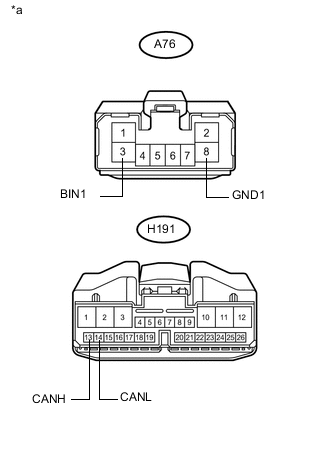
Text in Illustration *a Front view of wire harness connector
(to Engine Stop and Start ECU)
Disconnect the A76 and H191 engine stop and start ECU connectors.
-
Measure the resistance according to the value(s) in the table below.
-
-
HEADLIGHT LEVELING ECU (HEADLIGHT SWIVEL ECU ASSEMBLY)
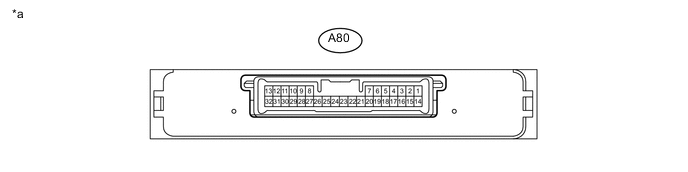
Text in Illustration *a Component without harness connected
(Headlight Leveling ECU (Headlight Swivel ECU Assembly))
- -
-
Disconnect the cable from the negative (-) battery terminal.
-
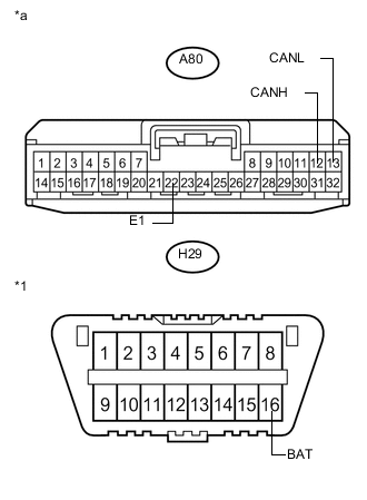
Text in Illustration *1 DLC3 *a Front view of wire harness connector
(to Headlight Leveling ECU (Headlight Swivel ECU Assembly))
Disconnect the A80 headlight leveling ECU (headlight swivel ECU assembly) connector.
-
Measure the resistance according to the value(s) in the table below.
-