GENERATOR INSPECTION

PROCEDURE
-
INSPECT GENERATOR PULLEY WITH CLUTCH
-
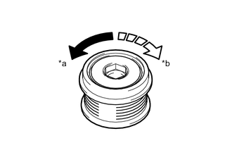
Text in Illustration *a Free *b Lock Hold the center of the generator pulley with clutch, and confirm that the outer ring turns counterclockwise and does not turn clockwise.
OK The outer ring turns counterclockwise and does not turn clockwise. If the result is not as specified, replace the generator pulley with clutch.
-
-
INSPECT GENERATOR DRIVE END FRAME BEARING
-
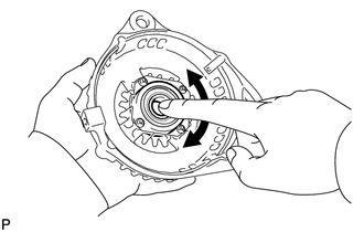
Check that the generator drive end frame bearing is not rough or worn and that it rotates smoothly.
If the generator drive end frame bearing is rough or worn, or does not rotate smoothly, replace the generator drive end frame bearing.
-
-
INSPECT GENERATOR BRUSH HOLDER ASSEMBLY
-
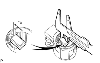
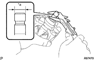
Text in Illustration *a Length Using a vernier caliper, measure the length of the exposed brushes.
Standard Exposed Brush Length 9.5 to 11.5 mm (0.374 to 0.453 in.) Minimum Exposed Brush Length 4.5 mm (0.177 in.) If the brush length is less than the minimum, replace the generator brush holder assembly.
-
-
INSPECT GENERATOR ROTOR ASSEMBLY
-
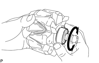
Check that the generator rotor bearing is not rough or worn and that it rotates smoothly.
If the generator rotor bearing is rough or worn, or does not rotate smoothly, replace the generator rotor assembly.
-
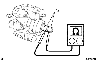
Text in Illustration *a Slip Ring Check the generator rotor assembly for an open circuit.
-
Measure the resistance according to the value(s) in the table below.
Standard Resistance Tester Connection Condition Specified Condition Slip ring - Slip ring Approx. 20°C (68°F) 1.5 to 1.9 Ω If the result is not as specified, replace the generator rotor assembly.
-
-
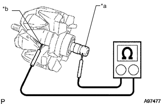
Text in Illustration *a Slip Ring *b Rotor Check the generator rotor assembly for a short to ground.
-
Measure the resistance according to the value(s) in the table below.
Standard Resistance Tester Connection Condition Specified Condition Slip ring - Rotor Always 10 MΩ or higher If the result is not as specified, replace the generator rotor assembly.
-
-
Check the slip ring.
-
Check that the slip rings are not rough or scored.
If the slip rings are rough or scored, replace the generator rotor assembly.
-
Text in Illustration *a Diameter Using a vernier caliper, measure the slip ring diameter.
Standard Diameter 14.2 to 14.8 mm (0.559 to 0.583 in.) Minimum Diameter 14 mm (0.551 in.) If the diameter is less than the minimum, replace the generator rotor assembly.
-
-