BLIND SPOT MONITOR SYSTEM Main Switch Circuit
DESCRIPTION
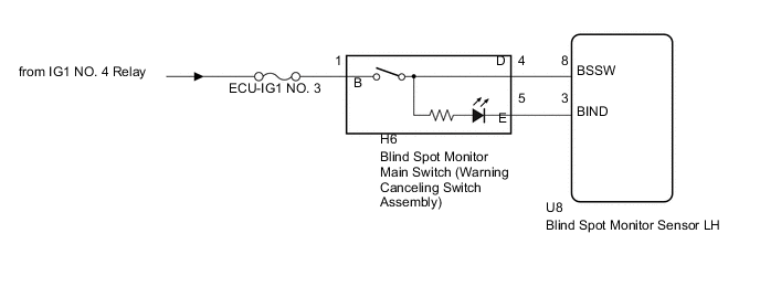
When the blind spot monitor main switch (warning canceling switch assembly) is turned on, a signal is sent to the blind spot monitor sensor LH and the blind spot monitor indicator on the blind spot monitor main switch (warning canceling switch assembly) illuminates. The blind spot monitor system operates according to this signal.
WIRING DIAGRAM
CAUTION / NOTICE / HINT
Note
Inspect the fuses for circuits related to this system before performing the following inspection procedure.
PROCEDURE
-
CHECK BLIND SPOT MONITOR MAIN SWITCH (WARNING CANCELING SWITCH)
-
Check that the blind spot monitor indicator on the blind spot monitor main switch (warning canceling switch assembly) illuminates normally when the blind spot monitor main switch (warning canceling switch assembly) is turned from off to on.
-
Check that the blind spot monitor indicator on the blind spot monitor main switch (warning canceling switch assembly) is turn off normally when the blind spot monitor main switch (warning canceling switch assembly) is turned from on to off.
OK The blind spot monitor indicator operates normally.
NG 
INSPECT BLIND SPOT MONITOR MAIN SWITCH (WARNING CANCELING SWITCH ASSEMBLY) Click here
OK 
-
-
READ VALUE USING GTS
-
Connect the GTS to the DLC3.
-
Turn the engine switch on (IG).
-
Turn the GTS on.
-
Enter the following menus: Body Electrical / Blind spot monitor Master / Data List.
-
According to the display on GTS, read the Data List.
Blind spot monitor Master Tester Display Measurement Item/Range Normal Condition Diagnostic Note Main Switch Blind spot monitor main switch (warning canceling switch assembly) / OFF or ON ON: Blind spot monitor main switch (warning canceling switch assembly) on
OFF: Blind spot monitor main switch (warning canceling switch assembly) off
- Result Result Proceed to The display does not change as shown above when the blind spot monitor main switch (warning canceling switch assembly) is operated. A The display changes as shown above when the blind spot monitor main switch (warning canceling switch assembly) is operated. B
B 
PROCEED TO NEXT SUSPECTED AREA SHOWN IN PROBLEM SYMPTOMS TABLE Click here
A
-
-
INSPECT BLIND SPOT MONITOR MAIN SWITCH (WARNING CANCELING SWITCH ASSEMBLY)
-
Remove the blind spot monitor main switch (warning canceling switch assembly) Click here.
-
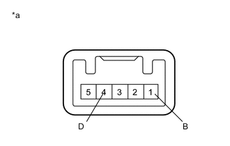
Text in Illustration *a Component without harness connected
(Blind Spot Monitor Main Switch (Warning Canceling Switch Assembly))
Measure the resistance according to the value(s) in the table below.
Standard Resistance Tester Connection Condition Specified Condition 1 (B) - 4 (D) Blind spot monitor main switch is on (not protruding) Below 1 Ω 1 (B) - 4 (D) Blind spot monitor main switch is off (protruding) 10 kΩ or higher
NG
REPLACE BLIND SPOT MONITOR MAIN SWITCH (WARNING CANCELING SWITCH ASSEMBLY) Click here
OK
-
-
CHECK HARNESS AND CONNECTOR (BLIND SPOT MONITOR MAIN SWITCH - BATTERY)
-
Disconnect the H6 blind spot monitor main switch (warning canceling switch assembly) connector.
-
Measure the voltage according to the value(s) in the table below.
Standard Voltage Tester Connection Condition Specified Condition H6-1 (B) - Body ground Engine switch on (IG) 11 to 14 V H6-1 (B) - Body ground Engine switch off Below 1 V
NG
REPAIR OR REPLACE HARNESS OR CONNECTOR
OK
-
-
CHECK HARNESS AND CONNECTOR (BLIND SPOT MONITOR MAIN SWITCH - BLIND SPOT MONITOR SENSOR LH)
-
Disconnect the U8 blind spot monitor sensor LH connector.
-
Measure the resistance according to the value(s) in the table below.
Standard Resistance Tester Connection Condition Specified Condition U8-8 (BSSW) - H6-4 (D) Always Below 1 Ω U8-8 (BSSW) - Body ground Always 10 kΩ or higher
OK
REPLACE BLIND SPOT MONITOR SENSOR LH Click here
NG
REPAIR OR REPLACE HARNESS OR CONNECTOR
-
-
INSPECT BLIND SPOT MONITOR MAIN SWITCH (WARNING CANCELING SWITCH ASSEMBLY)
-
Remove the blind spot monitor main switch (warning canceling switch assembly) Click here.
-
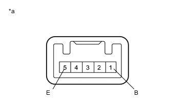
Text in Illustration *a Component without harness connected
(Blind Spot Monitor Main Switch (Warning Canceling Switch Assembly))
Apply battery voltage to the blind spot monitor main switch (warning canceling switch assembly) connector and check operation of the blind spot monitor indicator, as shown in the table below.
OK Connection Condition Specified Condition Battery positive (+) → Terminal 1 (B)
Battery negative (-) → Terminal 5 (E)
Blind spot monitor main switch is on (not protruding) Blind spot monitor indicator illuminates Battery positive (+) → Terminal 1 (B)
Battery negative (-) → Terminal 5 (E)
Blind spot monitor main switch is off (protruding) Blind spot monitor indicator not illuminate
NG
REPLACE BLIND SPOT MONITOR MAIN SWITCH (WARNING CANCELING SWITCH ASSEMBLY) Click here
OK
-
-
CHECK HARNESS AND CONNECTOR (BLIND SPOT MONITOR MAIN SWITCH - BLIND SPOT MONITOR SENSOR LH)
-
Disconnect the U8 blind spot monitor sensor LH connector.
-
Measure the resistance according to the value(s) in the table below.
Standard Resistance Tester Connection Condition Specified Condition U8-3 (BIND) - H6-5 (E) Always Below 1 Ω U8-3 (BIND) - Body ground Always 10 kΩ or higher
OK
REPLACE BLIND SPOT MONITOR SENSOR LH Click here
NG
REPAIR OR REPLACE HARNESS OR CONNECTOR
-