AUDIO AND VISUAL SYSTEM, Diagnostic DTC:B1579
| DTC Code | DTC Name |
|---|---|
| B1579 | Voice Recognition Microphone Disconnected |
DESCRIPTION
The radio receiver assembly and roof console box assembly (telephone microphone assembly) are connected to each other using the microphone connection detection signal lines.
This DTC is stored when a microphone connection detection signal line is disconnected.
| DTC No. | DTC Detection Condition | Trouble Area |
|---|---|---|
| B1579 | Telephone microphone signal is lost. |
|
-
*: w/ Manual (SOS) Switch
WIRING DIAGRAM
-
w/o Manual (SOS) Switch
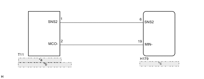
*a Roof Console Box Assembly *b (Telephone Microphone Assembly) *c Radio Receiver Assembly -
w/ Manual (SOS) Switch
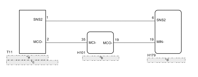
*a Roof Console Box Assembly *b Telematics Transceiver *c (Telephone Microphone Assembly) *d Radio Receiver Assembly
CAUTION / NOTICE / HINT
Note
-
Depending on the parts that are replaced during vehicle inspection or maintenance, performing initialization, registration or calibration may be needed. Refer to Precaution for Audio and Visual System.
PROCEDURE
-
INSPECT RADIO RECEIVER ASSEMBLY
-
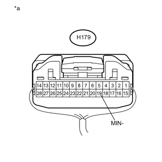
*a Component with harness connected
(Radio Receiver Assembly)
Measure the resistance according to the value(s) in the table below.
Standard Resistance Tester Connection Condition Specified Condition H179-19 (MIN-) - Body ground Always Below 1 Ω
NG 
REPLACE RADIO RECEIVER ASSEMBLY Click here
OK 
-
-
CONFIRM MODEL
-
Choose the model to be inspected.
Result Result Proceed to w/ Manual (SOS) Switch A w/o Manual (SOS) Switch B
B 
CHECK HARNESS AND CONNECTOR (RADIO RECEIVER ASSEMBLY - ROOF CONSOLE BOX ASSEMBLY (TELEPHONE MICROPHONE ASSEMBLY)) Click here
A
-
-
CHECK HARNESS AND CONNECTOR (TELEMATICS TRANSCEIVER - ROOF CONSOLE BOX ASSEMBLY (TELEPHONE MICROPHONE ASSEMBLY))
-
Disconnect the H101 telematics transceiver connector.
-
Disconnect the T11 roof console box assembly (telephone microphone assembly) connector.
-
Measure the resistance according to the value(s) in the table below.
Standard Resistance Tester Connection Condition Specified Condition H101-35 (MCI-) - T11-2 (MCO-) Always Below 1 Ω H101-35 (MCI-) or T11-2 (MCO-) - Body ground Always 10 kΩ or higher
NG
REPAIR OR REPLACE HARNESS OR CONNECTOR
OK
-
-
CHECK HARNESS AND CONNECTOR (RADIO RECEIVER ASSEMBLY - TELEMATICS TRANSCEIVER)
-
Disconnect the H179 radio receiver assembly connector.
-
Disconnect the H101 telematics transceiver connector.
-
Measure the resistance according to the value(s) in the table below.
Standard Resistance Tester Connection Condition Specified Condition H179-19 (MIN-) - H101-19 (MCO-) Always Below 1 Ω H179-19 (MIN-) or H101-19 (MCO-) - Body ground Always 10 kΩ or higher
NG
REPAIR OR REPLACE HARNESS OR CONNECTOR
OK
-
-
CHECK HARNESS AND CONNECTOR (RADIO RECEIVER ASSEMBLY - ROOF CONSOLE BOX ASSEMBLY (TELEPHONE MICROPHONE ASSEMBLY))
-
Disconnect the H179 radio receiver assembly connector.
-
Disconnect the T11 roof console box assembly (telephone microphone assembly) connector.
-
Measure the resistance according to the value(s) in the table below.
Standard Resistance Tester Connection Condition Specified Condition H179-6 (SNS2) - T11-1 (SNS2) Always Below 1 Ω H179-6 (SNS2) or T11-1 (SNS2) - Body ground Always 10 kΩ or higher
NG
REPAIR OR REPLACE HARNESS OR CONNECTOR
OK
-
-
INSPECT TELEMATICS TRANSCEIVER
-
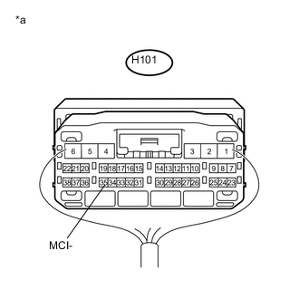
*a Component with harness connected
(Telematics Transceiver)
Measure the resistance according to the value(s) in the table below.
Standard Resistance Tester Connection Condition Specified Condition H101-35 (MCI-) - Body ground Always Below 1 Ω -
Proceed to the next step based on the inspection result.
Result Result Proceed to NG A OK B
A
REPLACE TELEMATICS TRANSCEIVER Click here
B
INSPECT ROOF CONSOLE BOX ASSEMBLY (TELEPHONE MICROPHONE ASSEMBLY) Click here
-
-
CHECK HARNESS AND CONNECTOR (RADIO RECEIVER ASSEMBLY - ROOF CONSOLE BOX ASSEMBLY (TELEPHONE MICROPHONE ASSEMBLY))
-
Disconnect the H179 radio receiver assembly connector.
-
Disconnect the T11 roof console box assembly (telephone microphone assembly) connector.
-
Measure the resistance according to the value(s) in the table below.
Standard Resistance Tester Connection Condition Specified Condition H179-19 (MIN-) - T11-2 (MCO-) Always Below 1 Ω H179-6 (SNS2) - T11-1 (SNS2) Always Below 1 Ω H179-19 (MIN-) or T11-2 (MCO-) - Body ground Always 10 kΩ or higher H179-6 (SNS2) or T11-1 (SNS2) - Body ground Always 10 kΩ or higher
NG
REPAIR OR REPLACE HARNESS OR CONNECTOR
OK
-
-
INSPECT ROOF CONSOLE BOX ASSEMBLY (TELEPHONE MICROPHONE ASSEMBLY)
-
Remove the roof console box assembly (telephone microphone assembly) Click here.
-
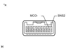
*a Component without harness connected
(Roof Console Box Assembly (Telephone Microphone Assembly))
Measure the resistance according to the value(s) in the table below.
Standard Resistance Tester Connection Condition Specified Condition 2 (MCO-) - 1 (SNS2) Always Below 1 Ω
OK
REPLACE RADIO RECEIVER ASSEMBLY Click here
NG
-
-
REPLACE TELEPHONE MICROPHONE ASSEMBLY
-
Replace the telephone microphone assembly with a new or known good one Click here.
-
Clear the DTCs Click here.
-
Recheck for DTCs and check that no DTCs are output.
OK No DTCs are output.
OK
END
NG
REPLACE ROOF CONSOLE BOX ASSEMBLY Click here
-