POWER STEERING SYSTEM Drive Mode Switch Circuit
DESCRIPTION
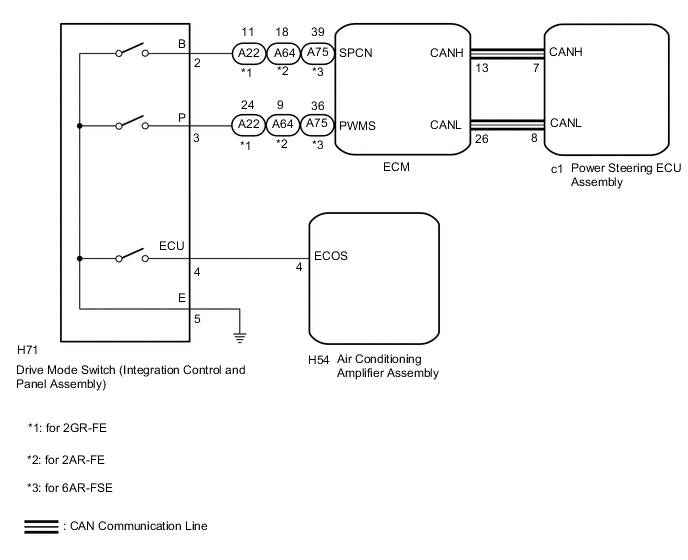
The electronic throttle and the EPS character change by the operation of the rotary type switch, and the drive mode corresponding to the running scene can be selected.
WIRING DIAGRAM
PROCEDURE
-
CHECK THE PROBLEM SYMPTOMS
-
Check each symptom by checking the suspected areas in the table below.
Result Result Proceed to SPORT mode or NORMAL mode is abnormal. A ECO mode is abnormal. B
B 
GO TO AIR CONDITIONING SYSTEM Click here
A 
-
-
CHECK CAN COMMUNICATION SYSTEM
-
Check for DTCs (See page for with Central Gateway ECU, Click here for without Central Gateway ECU).
Result Result Proceed to DTCs are not output. A DTCs are output. (w/ Central Gateway ECU) B DTCs are output. (w/o Central Gateway ECU) C
B
GO TO CAN COMMUNICATION SYSTEM (w/ Central Gateway ECU) Click here
C
GO TO CAN COMMUNICATION SYSTEM (w/o Central Gateway ECU) Click here
A
-
-
CHECK HARNESS AND CONNECTOR (DRIVE MODE SWITCH (INTEGRATION CONTROL AND PANEL ASSEMBLY) - BODY GROUND)
-
Turn the engine switch off.
-
Disconnect the H71 drive mode switch (integration control and panel assembly) connector.
-
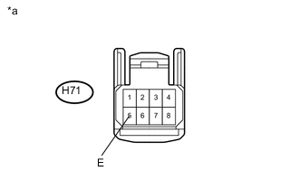
Text in Illustration *a Front view of wire harness connector
(to Drive Mode Switch (Integration Control and Panel Assembly)
Measure the resistance according to the value(s) in the table below.
Standard Resistance Tester Connection Specified Condition H71-5 (E) - Body ground Below 1 Ω
NG
REPAIR OR REPLACE HARNESS OR CONNECTOR
OK
-
-
INSPECT DRIVE MODE SWITCH (INTEGRATION CONTROL AND PANEL ASSEMBLY)
-
Inspect drive mode switch (integration control and panel assembly) Click here.
OK Drive mode switch (integration control and panel assembly) is normal.
NG
REPLACE INTEGRATION CONTROL AND PANEL ASSEMBLY Click here
OK
-
-
CHECK HARNESS AND CONNECTOR (DRIVE MODE SWITCH (INTEGRATION CONTROL AND PANEL ASSEMBLY) - ECM)
-
Reconnect the connector of the drive mode switch (integration control and panel assembly).
-
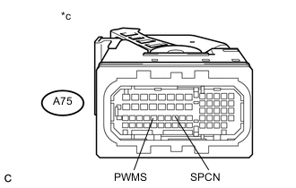
Disconnect the A22, A64 and A75 ECM connector.
-
Measure the resistance according to the value(s) in the table below.
Standard Resistance for 2GR-FE Tester Connection Condition Specified Condition A22-11 (SPCN) - Body ground SPORT mode switch being turned and held at SPORT position
(SPORT mode)
10 kΩ or higher ↑ NORMAL mode switch being pushed and held
(NORMAL mode)
Below 1 Ω A22-24 (PWMS) - Body ground SPORT mode switch not turned
(NORMAL mode)
10 kΩ or higher ↑ SPORT mode switch being turned and held at SPORT position
(SPORT mode)
Below 1 Ω for 2AR-FE Tester Connection Condition Specified Condition A64-18 (SPCN) - Body ground SPORT mode switch being turned and held at SPORT position
(SPORT mode)
10 kΩ or higher ↑ NORMAL mode switch being pushed and held
(NORMAL mode)
Below 1 Ω A64-9 (PWMS) - Body ground SPORT mode switch not turned
(NORMAL mode)
10 kΩ or higher ↑ SPORT mode switch being turned and held at SPORT position
(SPORT mode)
Below 1 Ω for 6AR-FSE Tester Connection Condition Specified Condition A75-39 (SPCN) - Body ground SPORT mode switch being turned and held at SPORT position
(SPORT mode)
10 kΩ or higher ↑ NORMAL mode switch being pushed and held
(NORMAL mode)
Below 1 Ω A75-36 (PWMS) - Body ground SPORT mode switch not turned
(NORMAL mode)
10 kΩ or higher ↑ SPORT mode switch being turned and held at SPORT position
(SPORT mode)
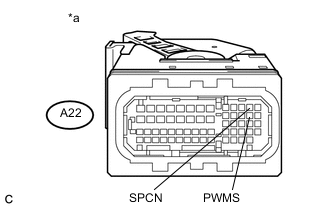
Below 1 Ω Text in Illustration *a Front view of wire harness connector
(to ECM (for 2GR-FE))
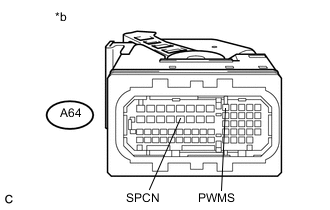
*b Front view of wire harness connector
(to ECM (for 2AR-FE))
*c Front view of wire harness connector
(to ECM (for 6AR-FSE))
Result Result Proceed to OK (for 2GR-FE) A OK (for 2AR-FE) B OK (for 6AR-FSE) C NG D
A
REPLACE ECM Click here
B
REPLACE ECM Click here
C
REPLACE ECM Click here
D
REPAIR OR REPLACE HARNESS OR CONNECTOR
-