POWER STEERING SYSTEM, Diagnostic DTC:C1552, C1554
| DTC Code | DTC Name |
|---|---|
| C1552 | PIG Power Supply Voltage |
| C1554 | Power Supply Relay Failure |
DESCRIPTION
When a problem occurs in the system, the power source relay circuit and the motor relay circuit are shut off to stop the power assist. The ECU must be replaced when there is a problem with the relays because the relays are built into the ECU.
| DTC No. | DTC Detection Condition | Trouble Area |
|---|---|---|
| C1552 | PIG power source circuit malfunction |
|
| C1554 | Power source relay circuit malfunction |
|
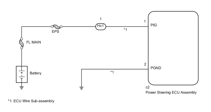
WIRING DIAGRAM
CAUTION / NOTICE / HINT
Note
If the power steering ECU assembly has been replaced with a new one, perform assist map writing and torque sensor zero point calibration Click here.
Tech Tips
Inspect the fuses for circuits related to this system before performing the following inspection procedure.
PROCEDURE
-
CHECK CONNECTOR CONNECTION CONDITION AND GROUND WIRE
-
Check the connection condition of the ECU wire sub-assembly and power steering ECU assembly connectors.
OK The ECU wire sub-assembly and power steering ECU assembly connectors are securely connected. -
Check that the ground wire is securely installed with the bolt Click here.
OK The ground wire is securely installed with the bolt.
NG 
CONNECT CONNECTOR OR INSTALL GROUND WIRE Click here
OK 
-
-
READ VALUE USING GTS
-
Turn the engine switch off.
-
Connect the GTS to the DLC3.
-
Turn the engine switch on (IG).
-
Turn the GTS on.
-
Enter the following menus: Chassis / EMPS / Data List.
-
Select the item "PIG Power Supply" in the Data List and read the value displayed on the GTS.
EMPS Tester Display Measurement Item/Range Normal Condition Diagnostic Note PIG Power Supply Power source voltage to active motor/
Min.: 0.0000 V
Max.: 20.1531 V
9 to 16 V Always OK The normal condition value is displayed on the GTS. Result Result Proceed to OK (for Manual tilt and manual telescopic steering column) A OK (for Power tilt and power telescopic steering column) B NG C
A
REPLACE POWER STEERING ECU ASSEMBLY Click here
B
REPLACE POWER STEERING ECU ASSEMBLY Click here
C
-
-
CHECK HARNESS AND CONNECTOR (BATTERY - ECU WIRE SUB-ASSEMBLY)
-
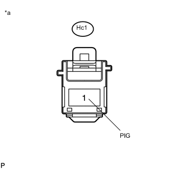
Text in Illustration *a Front view of wire harness connector
(to ECU Wire Sub-assembly)
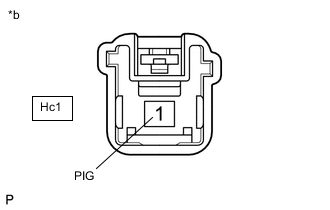
Disconnect the Hc1 ECU wire sub-assembly connector.
-
Measure the voltage according to the value(s) in the table below.
Standard Voltage Tester Connection Condition Specified Condition Hc1-1 (PIG) - Body ground Always 9 to 16 V
NG
REPAIR OR REPLACE HARNESS OR CONNECTOR
OK
-
-
CHECK ECU WIRE SUB-ASSEMBLY (POWER STEERING ECU ASSEMBLY - BODY GROUND)
-
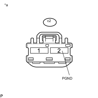
Text in Illustration *a Front view of wire harness connector
(to Power Steering ECU Assembly)
Disconnect the c2 power steering ECU assembly connector.
-
Measure the resistance according to the value(s) in the table below.
Standard Resistance Tester Connection Condition Specified Condition c2-2 (PGND) - Body ground Always Below 1 Ω
NG
REPAIR OR REPLACE ECU WIRE SUB-ASSEMBLY Click here
OK
-
-
INSPECT ECU WIRE SUB-ASSEMBLY
-
Measure the resistance according to the value(s) in the table below.
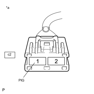
Standard Resistance Tester Connection Condition Specified Condition c2-1 (PIG) - Hc1-1 (PIG) Always Below 1 Ω Text in Illustration *a Front view of wire harness connector
(to Power Steering ECU Assembly)
*b Front view of wire harness connector
(to Vehicle Wire Harness)
Result Result Proceed to OK (for Manual tilt and manual telescopic steering column) A OK (for Power tilt and power telescopic steering column) B NG C
A
REPLACE POWER STEERING ECU ASSEMBLY Click here
B
REPLACE POWER STEERING ECU ASSEMBLY Click here
C
REPAIR OR REPLACE ECU WIRE SUB-ASSEMBLY Click here
-