VEHICLE STABILITY CONTROL SYSTEM TEST MODE PROCEDURE

-
WARNING LIGHT AND INDICATOR LIGHT INITIAL CHECK
-
When the engine switch is turned on (IG), check that the ABS warning, brake warning, VSC OFF indicator and slip indicator lights all come on for approximately 3 seconds.
Tech Tips
-
When the brake fluid level is low, the brake warning light comes on.
-
If the skid control ECU (brake actuator assembly) stores any DTCs, the ABS warning and slip indicator lights will come on.
-
If any of the indicators remain on or do not come on, proceed to troubleshooting for the light circuits listed below.
Trouble Area See Procedure ABS warning light circuit (Remains on) ABS warning light circuit (Does not come on) Brake warning light circuit (Remains on) Brake warning light circuit (Does not come on) VSC OFF indicator light circuit (Remains on) VSC OFF indicator light circuit (Does not come on) Slip indicator light circuit (Remains on) Slip indicator light circuit (Does not come on) -
-
-
SENSOR CHECK USING TEST MODE (SIGNAL CHECK) (When Using GTS)
Tech Tips
-
VSC does not operate in Test Mode (signal check), regardless of whether the sensor check is normal or abnormal.
-
When a malfunction occurs in an ABS system sensor, the ABS warning light illuminates.
-
When a malfunction occurs in a VSC system sensor, the slip indicator light illuminates.
-
Procedure to enter Test Mode (signal check).
-
Turn the engine switch on (IG).
-
Make sure the shift lever is in P.
-
Apply the parking brake.
-
Put the steering wheel in the neutral position.
-
Turn the engine switch off and connect the GTS to the DLC3.
-
Turn the engine switch on (IG) and turn the GTS on.
-
Enter the following menus: Chassis / ABS/VSC/TRC / Utility / Signal Check.
Tech Tips
Signals related to the VSC system can be inspected by performing a Test Mode (signal check) inspection. During the inspection, the display of items determined normal by the skid control ECU (brake actuator assembly) changes from incomplete to complete.
-
-
Acceleration Sensor Check
-
Enter Test Mode (signal check).
-
Keep the vehicle stationary on a level surface for 1 second or more.
Tech Tips
The acceleration sensor check can be performed with the master cylinder pressure sensor check below.
-
-
Lost Booster Pressure Judgment Check and Master Cylinder Pressure Sensor Zero Point Calibration
-
Depress the brake pedal several times to release vacuum from the brake booster assembly with the engine stopped.
-
Turn the engine switch on (IG).
-
Check that the brake warning light comes on when depressing the brake pedal with a force of 59.0 N (6.0 kgf, 13.2 lbf) or more for 1 second or more. (The lost booster pressure state is judged to be normal.)
-
Start the engine while depressing the brake pedal with a force of 59.0 N (6.0 kgf, 13.2 lbf) or more for 1 second or more.
-
Check that the brake warning light goes off when quickly releasing the brake pedal. (The lost booster pressure state is judged to be normal.)
-
Leave the vehicle for 1 second or more. (Master cylinder pressure sensor zero point calibration)
Note
-
If the brake pedal is depressed slowly or repeatedly, the master cylinder pressure sensor zero point calibration will not complete normally.
-
If the lost booster pressure judgment check results are not normal, then the master cylinder pressure sensor check cannot be performed.
-
If rechecking after the engine has started, end Test Mode, enter Test Mode again, and release vacuum in the booster by pumping the brake pedal prior to rechecking.
Tech Tips
If the lost booster pressure state is not judged to be normal, the brake warning light comes on and Test Mode (signal check) inspection item (Output Master Cylinder Pressure Sensor) is displayed.
-
-
-
Master Cylinder Pressure Sensor Check
-
Enter Test Mode (signal check).
-
Start the engine.
-
Leave the vehicle in a stationary condition and release the brake pedal for 1 second or more, and quickly and continuously depress the brake pedal with a force greater than 98 N (10 kgf, 22.0 lbf) for 1 second.
-
Check that the ABS warning light stays on for 3 seconds.
Tech Tips
-
Ensure that the ABS warning light comes on.
-
While the ABS warning light stays on, continue to depress the brake pedal with a force of 98 N (10 kgf, 22 lbf) or more.
-
The ABS warning light comes on for 3 seconds every time the brake pedal operation above is performed.
-
If the master cylinder pressure sensor check is not completed, depressing the brake pedal causes further decreases in vacuum in the brake booster, making the sensor check difficult to complete.
-
If the vacuum is insufficient, the master cylinder pressure sensor check may not be completed. In this case, run the engine at idle to obtain sufficient vacuum.
-
If the brake pedal is strongly depressed when the vacuum is insufficient, the brake warning light may come on in accordance with booster pressure control. In this case, run the engine at idle to obtain sufficient vacuum.
-
-
-
Speed Sensor Check
Note
Before performing the speed sensor signal check, complete the acceleration sensor and master cylinder pressure sensor checks.
-
Enter Test Mode (signal check).
-
Start the engine.
-
Drive the vehicle straight ahead.
Accelerate the vehicle to a speed of 45 km/h (28 mph) or more for several seconds and check that the ABS warning light goes off.
-
The sensor check may not complete if wheelspin occurs.
-
The ABS warning light blinks when the sensor check has been completed and the brake pedal is depressed.
-
The ABS warning light comes on immediately after a malfunction has been detected during the speed sensor check.
-
-
Stop the vehicle.
Note
-
The speed sensor check may not complete if the sensor check is started with the steering wheel turned or one or more wheels spinning.
-
After the ABS warning light goes off and if the vehicle speed exceeds 80 km/h (50 mph), a sensor check code will be stored again. Decelerate or stop the vehicle before the speed reaches 80 km/h (50 mph).
-
If the sensor check has not been completed, the ABS warning light blinks during driving and the ABS system does not operate.
Tech Tips
When the sensor check has been completed, the ABS warning light remains off during driving and blinks in the Test Mode (signal check) pattern while the vehicle is stationary.
-
-
-
VSC Sensor Check
Tech Tips
Check that the slip indicator light is blinking in the Test Mode pattern before performing the following VSC sensor check.
-
VSC OFF Switch (Integration control and panel assembly) Check
-
Press the VSC OFF switch (Integration control and panel assembly).
-
Check that the VSC OFF indicator light comes on.
-
Press the VSC OFF switch (Integration control and panel assembly) again.
-
-
End of Sensor Check
-
If the sensor check is completed, the ABS warning light and slip indicator light blink (Test Mode (signal check)) when the vehicle stops and the ABS warning light is off while the vehicle is being driven.
Note
-
When Test Mode (signal check) is started with the GTS and all items display complete, the sensor check ends.
-
If the sensor check is not complete, the ABS warning light blinks when the vehicle is in motion and the ABS does not operate.
-
If a DTC is detected in Test Mode (signal check), the ABS warning light or slip indicator light illuminates.
-
-
-
End of Test Mode (Signal Check)
-
End Test Mode (signal check) using the GTS
-
Turn the engine switch off and enter normal mode.
-
Remove the GTS.
-
-
-
Test Mode (Signal Check) Inspection Item Chart
Item Name Range Judgment Description Trouble Area Output Signal of Front Speed Sensor RH Incomplete/complete Check for foreign matter, check the gap between the sensor and rotor
-
Open or short in speed sensor
-
Open or short in sensor system wire harness
-
Defective connector contact or increased terminal resistance
-
Speed sensor installation defect
-
Sensor rotor system malfunction
Output Signal of Front Speed Sensor LH Incomplete/complete Check for foreign matter, check the gap between the sensor and rotor
-
Open or short in speed sensor
-
Open or short in sensor system wire harness
-
Defective connector contact or increased terminal resistance
-
Speed sensor installation defect
-
Sensor rotor system malfunction
Output Signal of Rear Speed Sensor RH Incomplete/complete Check for foreign matter, check the gap between the sensor and rotor
-
Open or short in speed sensor
-
Open or short in sensor system wire harness
-
Defective connector contact or increased terminal resistance
-
Speed sensor installation defect
-
Sensor rotor system malfunction
Output Signal of Rear Speed Sensor LH Incomplete/complete Check for foreign matter, check the gap between the sensor and rotor
-
Open or short in speed sensor
-
Open or short in sensor system wire harness
-
Defective connector contact or increased terminal resistance
-
Speed sensor installation defect
-
Sensor rotor system malfunction
Change in Output Signal of Front Speed Sensor RH Incomplete/complete Check the stability of the sensor input waveform
-
Foreign object attached to speed sensor
-
Sensor rotor system malfunction
Change in Output Signal of Front Speed Sensor LH Incomplete/complete Check the stability of the sensor input waveform
-
Foreign object attached to speed sensor
-
Sensor rotor system malfunction
Change in Output Signal of Rear Speed Sensor RH Incomplete/complete Check the stability of the sensor input waveform
-
Foreign object attached to speed sensor
-
Sensor rotor system malfunction
Change in Output Signal of Rear Speed Sensor LH Incomplete/complete Check the stability of the sensor input waveform
-
Foreign object attached to speed sensor
-
Sensor rotor system malfunction
Output Voltage Deceleration Sensor Incomplete/complete Check the acceleration sensor output voltage
-
Acceleration sensor zero point stored incorrectly
-
Acceleration sensor (airbag sensor assembly) connector connection malfunction
-
Acceleration sensor (airbag sensor assembly) internally stuck
-
Defective acceleration sensor (airbag sensor assembly) installation
Memory System Information Incomplete/complete Check stored system information (skid control ECU (brake actuator assembly)) against vehicle specification
-
ECM incorrectly installed
-
Brake actuator assembly incorrectly installed
-
CAN communication between ECM and skid control ECU (brake actuator assembly)
Output Master Cylinder Pressure Sensor Incomplete/complete
-
Check the master cylinder pressure sensor zero point voltage
-
Check that the sensitivity of the master cylinder pressure sensor is normal
-
Open circuit or short in master cylinder pressure sensor circuit
-
Open or short in stop light switch assembly circuit or defective connector connection
-
Stop light switch assembly stuck OFF
Judgment of Failure State Incomplete/complete Check that the brake pedal load sensing switch is normal
-
Open or short in brake pedal load sensing switch system wire harness
-
Brake pedal load sensing switch stuck ON/OFF
-
-
-
ACTIVATE TEST MODE (SIGNAL CHECK) (When not Using GTS)
Tech Tips
-
VSC does not operate in Test Mode (signal check), regardless of whether the sensor check is normal or abnormal.
-
When a malfunction occurs in an ABS system sensor, the ABS warning light illuminates.
-
When a malfunction occurs in a VSC system sensor, the slip indicator light illuminates.
-
Procedure to enter Test Mode (signal check).
-
Turn the engine switch on (IG).
-
Make sure the shift lever is in P.
-
Apply the parking brake.
-
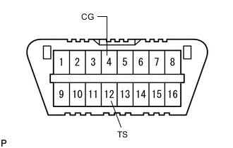
Text in Illustration *a Front view of DLC3 Put the steering wheel in the neutral position.
-
Turn the engine switch off.
-
Using SST, connect terminals 12 (TS) and 4 (CG) of the DLC3.
- SST
- 09843-18040
-
Turn the engine switch on (IG).
-
Check that the ABS warning and slip indicator lights come on for several seconds and then blink in Test Mode (signal check).
Tech Tips
If the ABS warning and slip indicator lights do not blink, inspect the TS and CG terminal circuit and ABS warning and slip indicator light circuits.
Trouble Area See Procedure TS and CG terminal circuit ABS warning light circuit (Remains on) ABS warning light circuit (Does not come on) Slip indicator light circuit (Remains on) Slip indicator light circuit (Does not come on)
-
-
-
ACCELERATION SENSOR CHECK
-
Enter Test Mode (signal check).
-
Keep the vehicle stationary on a level surface for 1 second or more.
Tech Tips
The acceleration sensor check can be performed with the master cylinder pressure sensor check below.
-
Lost Booster Pressure Judgment Check and Master Cylinder Pressure Sensor Zero Point Calibration
-
Depress the brake pedal several times to release vacuum from the brake booster assembly with the engine stopped.
-
Turn the engine switch on (IG).
-
Check that the brake warning light comes on when depressing the brake pedal with a force of 59.0 N (6.0 kgf, 13.2 lbf) or more for 1 second or more. (The lost booster pressure state is judged to be normal.)
-
Start the engine while depressing the brake pedal with a force of 59.0 N (6.0 kgf, 13.2 lbf) or more for 1 second or more.
-
Check that the brake warning light goes off when quickly releasing the brake pedal. (The lost booster pressure state is judged to be normal.)
-
Leave the vehicle for 1 second or more. (Master cylinder pressure sensor zero point calibration)
Note
-
If the brake pedal is depressed slowly or repeatedly, the master cylinder pressure sensor zero point calibration will not complete normally.
-
If the lost booster pressure judgment check results are not normal, then the master cylinder pressure sensor check cannot be performed.
-
If rechecking after the engine has started, end Test Mode, enter Test Mode again, and release vacuum in the booster by pumping the brake pedal prior to rechecking.
Tech Tips
If the lost booster pressure state is not judged to be normal, the brake warning light comes on and Test Mode (signal check) inspection item (Output Master Cylinder Pressure Sensor) is displayed.
-
-
-
-
MASTER CYLINDER PRESSURE SENSOR CHECK
-
Enter Test Mode (signal check).
-
Start the engine.
-
Leave the vehicle in a stationary condition and release the brake pedal for 1 second or more, and quickly and continuously depress the brake pedal with a force of 98 N (10 kgf, 22 lbf) or more for 1 second.
-
Check that the ABS warning light stays on for 3 seconds.
Tech Tips
-
Ensure that the ABS warning light comes on.
-
While the ABS warning light stays on, continue to depress the brake pedal with a force of 98 N (10 kgf, 22 lbf) or more.
-
The ABS warning light comes on for 3 seconds every time the brake pedal operation above is performed.
-
If the master cylinder pressure sensor check is not completed, depressing the brake pedal causes further decreases in vacuum in the brake booster, making the sensor check difficult to complete.
-
If the vacuum is insufficient, the master cylinder pressure sensor check may not be completed. In this case, run the engine at idle to obtain sufficient vacuum.
-
If the brake pedal is strongly depressed when the vacuum is insufficient, the brake system warning light (red indicator) may come on in accordance with booster pressure control. In this case, run the engine at idle to obtain sufficient vacuum.
-
-
-
SPEED SENSOR CHECK
Note
Before performing the speed sensor signal check, complete the acceleration sensor and master cylinder pressure sensor checks.
-
Enter Test Mode (signal check).
-
Start the engine.
-
Drive the vehicle straight ahead.
Accelerate the vehicle to a speed of 45 km/h (28 mph) or more for several seconds and check that the ABS warning light goes off.
-
The sensor check may not be completed if wheelspin occurs.
-
The ABS warning light blinks when the sensor check has been completed and the brake pedal is depressed.
-
The ABS warning light comes on immediately after a malfunction has been detected during the speed sensor check.
-
-
Stop the vehicle.
Note
-
The speed sensor check may not be completed if the sensor check is started with the steering wheel turned or one or more wheels spinning.
-
After the ABS warning light goes off and if the vehicle speed exceeds 80 km/h (50 mph), a sensor check code will be stored again. Decelerate or stop the vehicle before the speed reaches 80 km/h (50 mph).
-
If the sensor check has not been completed, the ABS warning light blinks during driving and the ABS system does not operate.
Tech Tips
When the sensor check has been completed, the ABS warning light remains off during driving and blinks in the Test Mode (signal check) pattern while the vehicle is stationary.
-
-
VSC Sensor Check
Tech Tips
Check that the slip indicator light is blinking in the Test Mode pattern before performing the following VSC sensor check.
-
VSC OFF Switch (Integration control and panel assembly) Check
-
Press the VSC OFF switch (Integration control and panel assembly).
-
Check that the VSC OFF indicator light comes on.
-
Press the VSC OFF switch (Integration control and panel assembly) again.
-
-
-
END OF SENSOR CHECK
-
If the sensor check is completed, the ABS warning light and slip indicator light blink (Test Mode (signal check)) when the vehicle stops and the ABS warning light is off while the vehicle is being driven.
Note
-
When Test Mode (signal check) is started with the GTS and all items display complete, the sensor check ends.
-
If the sensor check is not complete, the ABS warning light blinks when the vehicle is in motion and the ABS does not operate.
-
If a DTC is detected in Test Mode (signal check), the ABS warning light or slip indicator light illuminates.
-
-
-
END OF TEST MODE (SIGNAL CHECK)
-
End Test Mode (signal check) using the GTS
-
Turn the engine switch off and enter normal mode.
-
Remove the GTS.
-
-
End Test Mode (signal check) by connecting DLC3 terminals
-
Turn the engine switch off and disconnect terminals 13 (TC), 12 (TS) and 4 (CG) of the DLC3.
-
Turn the engine switch on (IG).
Tech Tips
-
Test Mode (signal check) is continued if 12 (TS) and 4 (CG) are disconnected while the engine switch is on (IG).
-
If the engine switch is turned on (IG) with terminals 12 (TS) and 4 (CG) connected, the previous Test Mode (signal check) is maintained.
-
-
-
Sensor Check DTCs
ABS Sensor DTC No. Detection Item Trouble Area 71 Low Output Signal of Front Speed Sensor RH
-
Front speed sensor RH
-
Sensor installation
-
Front speed sensor rotor RH (Front drive outboard joint shaft assembly RH)
72 Low Output Signal of Front Speed Sensor LH
-
Front speed sensor LH
-
Sensor installation
-
Front speed sensor rotor LH (Front drive outboard joint shaft assembly LH)
73 Low Output Signal of Rear Speed Sensor RH
-
Rear speed sensor RH
-
Sensor installation
-
Rear speed sensor rotor RH (Rear axle hub and bearing assembly RH)
74 Low Output Signal of Rear Speed Sensor LH
-
Rear speed sensor LH
-
Sensor installation
-
Rear speed sensor rotor LH (Rear axle hub and bearing assembly LH)
75 Abnormal Change in Output Signal of Front Speed Sensor RH Front speed sensor rotor RH (Front drive outboard joint shaft assembly RH) 76 Abnormal Change in Output Signal of Front Speed Sensor LH Front speed sensor rotor LH (Front drive outboard joint shaft assembly LH) 77 Abnormal Change in Output Signal of Rear Speed Sensor RH Rear speed sensor rotor RH (Rear axle hub and bearing assembly RH) 78 Abnormal Change in Output Signal of Rear Speed Sensor LH Rear speed sensor rotor LH (Rear axle hub and bearing assembly LH) 79 Acceleration Sensor Output Voltage Malfunction
-
Sensor installation
-
Acceleration sensor (Airbag sensor assembly)
81 Master Cylinder Pressure Sensor Output Malfunction
-
Stop light switch assembly
-
Brake pedal load sensing switch (Brake pedal support assembly)
-
Brake booster assembly
-
Master cylinder pressure sensor (Brake actuator assembly)
Tech Tips
The codes in this table are output only in Test Mode (signal check).
-
-