TIRE PRESSURE WARNING SYSTEM TC and CG Terminal Circuit
DESCRIPTION
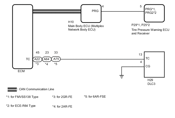
Tire pressure warning system DTCs can be checked by connecting terminals 13 (TC) and 4 (CG) of the DLC3. The DTCs are indicated by blinking the tire pressure warning light.
WIRING DIAGRAM
PROCEDURE
-
CHECK CAN COMMUNICATION SYSTEM
-
Check if CAN communication system DTCs are output (See page for w/ Central Gateway ECU or Click here for w/o Central Gateway ECU).
Result Result Proceed to DTCs are not output. A DTCs are output (w/ Central Gateway ECU). B DTCs are output (w/o Central Gateway ECU). C
B 
GO TO CAN COMMUNICATION SYSTEM Click here
C
GO TO CAN COMMUNICATION SYSTEM Click here
A 
-
-
CHECK DTC (C2179/79)
-
Check if DTC C2179/79 is output Click here.
Result Result Proceed to DTC C2179/79 is not output. A DTC C2179/79 is output. B
B
GO TO DTC C2179/79 Click here
A
-
-
CHECK HARNESS AND CONNECTOR (TC of DLC3 - ECM)
-
Disconnect the A22, A64 or A75 ECM connector.
-
Measure the resistance according to the value(s) in the table below.
Standard Resistance for 2GR-FE Tester Connection Condition Specified Condition H29-13 (TC) - A22-45 (TC) Always Below 1 Ω H29-13 (TC) or A22-45 (TC) - Body ground Always 10 kΩ or higher for 2AR-FE Tester Connection Condition Specified Condition H29-13 (TC) - A64-23 (TC) Always Below 1 Ω H29-13 (TC) or A64-23 (TC) - Body ground Always 10 kΩ or higher for 6AR-FSE Tester Connection Condition Specified Condition H29-13 (TC) - A75-33 (TC) Always Below 1 Ω H29-13 (TC) or A75-33 (TC) - Body ground Always 10 kΩ or higher
NG
REPAIR OR REPLACE HARNESS OR CONNECTOR
OK
-
-
CHECK HARNESS AND CONNECTOR (CG of DLC3 - BODY GROUND)
-
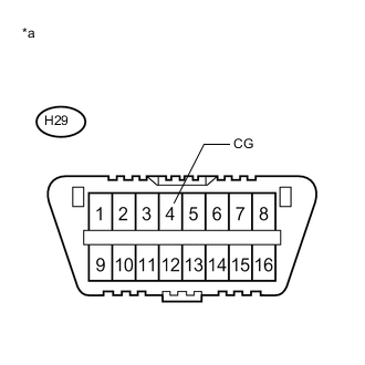
Text in Illustration *a Front view of DLC3 Measure the resistance according to the value(s) in the table below.
Standard Resistance Tester Connection Condition Specified Condition H29-4 (CG) - Body ground Always Below 1 Ω
NG
REPAIR OR REPLACE HARNESS OR CONNECTOR
OK
-
-
INSPECT DLC3 (TC VOLTAGE)
-
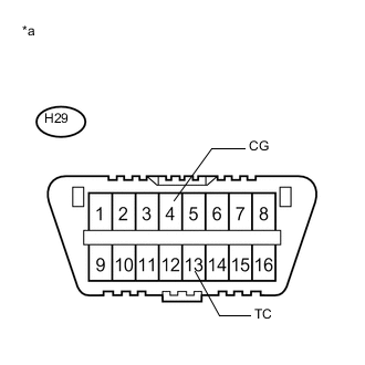
Text in Illustration *a Front view of DLC3 Reconnect the A22, A64 or A75 ECM connector.
-
Measure the voltage according to the value(s) in the table below.
Standard Voltage Tester Connection Condition Specified Condition H29-13 (TC) - H29-4 (CG) Engine switch on (IG) 11 to 14 V Result Result Proceed to OK A NG (for 2GR-FE) B NG (for 2AR-FE) C NG (for 6AR-FSE) D
A
PROCEED TO NEXT SUSPECTED AREA SHOWN IN PROBLEM SYMPTOMS TABLE Click here
B
REPLACE ECM Click here
C
REPLACE ECM Click here
D
REPLACE ECM Click here
-