VEHICLE STABILITY CONTROL SYSTEM, Diagnostic DTC:C1428

| DTC Code | DTC Name |
|---|---|
| C1428 | Motor Circuit Malfunction |
DESCRIPTION
| DTC No. | DTC Detection Condition | Trouble Area |
|---|---|---|
| C1428 | With the motor relay and motor fail-safe relay OFF, open or short in motor circuit continues for 2 seconds or more. | Brake actuator assembly (motor circuit) |
WIRING DIAGRAM
Refer to DTCs C1427 Click here.
CAUTION / NOTICE / HINT
Note
-
When replacing the pump motor (brake actuator assembly), perform zero point calibration and store system information Click here.
-
Inspect the fuses for circuits related to this system before performing the following inspection procedure.
PROCEDURE
-
CHECK HARNESS AND CONNECTOR (GND2 TERMINAL)
-
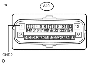
Text in Illustration *a Front view of wire harness connector
(to Skid Control ECU (Brake Actuator Assembly))
Make sure that there is no looseness at the locking part and the connecting part of the connectors.
-
Disconnect the A40 skid control ECU (brake actuator assembly) connector.
-
Measure the resistance according to the value(s) in the table below.
Standard Resistance Tester Connection Condition Specified Condition A40-1 (GND2) - Body ground Always Below 1 Ω
OK 
REPLACE BRAKE ACTUATOR ASSEMBLY Click here
NG
REPAIR OR REPLACE HARNESS OR CONNECTOR (GND2 CIRCUIT)
-