AUTOMATIC TRANSAXLE SYSTEM TERMINALS OF ECM

-
ECM
Tech Tips
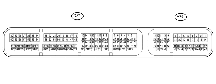
The standard voltage between each pair of ECM terminals is shown in the table below. The appropriate conditions for checking each pair of terminals are also indicated. The result of checks should be compared with the standard voltage for that pair of terminals shown in the "Specified Condition" column. The illustration above can be used as a reference to identify the ECM terminal locations.
Terminal No. (Symbol) Wiring Color Terminal Description Condition Specified Condition D87-1 (SLT+) - D87-31 (SLT-) LG - Y Shift solenoid valve SLT signal Engine idling Pulse generation D87-3 (SLU+) - D87-2 (SLU-) L - G Shift solenoid valve SLU signal All gears
(Lock-up on / Flex lock-up on)
Pulse generation D87-5 (SL2+) - D87-4 (SL2-) LG - GR Shift solenoid valve SL2 signal 4th, 5th or 6th gear Pulse generation D87-7 (SL3+) - D87-6 (SL3-) L - P Shift solenoid valve SL3 signal 2nd or 6th gear Pulse generation D87-13 (SL4+) - D87-12 (SL4-) V - W Shift solenoid valve SL4 signal 3rd or 5th gear Pulse generation D87-15 (SL1+) - D87-14 (SL1-) V - B Shift solenoid valve SL1 signal 1st, 2nd, 3rd or 4th gear Pulse generation D87-34 (D) - D87-53 (E1) G - W-B D shift position switch signal Engine switch on (IG) and shift lever in D or S 11 to 14 V Engine switch on (IG) and shift lever not in D or S Below 1 V D87-35 (R) - D87-53 (E1) GR - W-B R shift position switch signal Engine switch on (IG) and shift lever in R 11 to 14 V Engine switch on (IG) and shift lever not in R Below 1 V D87-64 (P) - D87-53 (E1) B - W-B P shift position switch signal Engine switch on (IG) and shift lever in P 11 to 14 V Engine switch on (IG) and shift lever not in P Below 1 V D87-65 (N) - D87-53 (E1) L - W-B N shift position switch signal Engine switch on (IG) and shift lever in N 11 to 14 V Engine switch on (IG) and shift lever not in N Below 1 V D87-71 (NTB) - D87-53 (E1) B - W-B Power source for sensor (fixed voltage) Engine switch on (IG) 11 to 14 V D87-72 (NTO) - D87-53 (E1) R - W-B Input speed sensor NT signal Engine idle speed Pulse generation D87-73 (NCB) - D87-53 (E1) LG - W-B Power source for sensor (fixed voltage) Engine switch on (IG) 11 to 14 V D87-74 (NCO) - D87-53 (E1) W - W-B Output speed sensor NC signal Vehicle driving Pulse generation D87-75 (SL) - D87-53 (E1) R - W-B Shift solenoid valve SL signal All gears
(Lock-up on / Flex lock-up on)
11 to 14 V D87-84 (THO1) - D87-83 (ETHO) LG - P ATF temperature sensor signal ATF temperature: 115°C (239°F) or more Below 1.5 V A75-1 (BATT) - D87-53 (E1) GR - W-B Battery (for measuring battery voltage and for ECM memory) Always 11 to 14 V A75-9 (STP) - D87-53 (E1) BE - W-B Stop light switch assembly signal Brake pedal depressed 7.5 to 14 V Brake pedal released Below 1.5 V A75-29 (STA) - D87-53 (E1) LG - W-B Starter assembly signal Cranking 5.5 V or higher A75-42 (SFTU) - D87-53 (E1) R - W-B Up shift switch signal Engine switch on (IG) and shift lever in S 11 to 14 V Engine switch on (IG) and shift lever held in "+" (Up shift) Below 1 V A75-43 (SFTD) - D87-53 (E1) L - W-B Down shift switch signal Engine switch on (IG) and shift lever in S 11 to 14 V Engine switch on (IG) and shift lever held in "-" (Down shift) Below 1 V A75-44 (SPD) - D87-53 (E1) L - W-B Vehicle speed signal from combination meter assembly signal Driving at 20 km/h (12 mph) Pulse generation A75-57 (NSW) - D87-53 (E1) LG - W-B Park/neutral position switch assembly signal Engine switch on (IG) and shift lever in P or N Below 2 V Engine switch on (IG) and shift lever not in P or N 11 to 14 V A75-59 (S) - D87-53 (E1) Y - W-B S shift position switch signal Engine switch on (IG) and shift lever in S 11 to 14 V Engine switch on (IG) and shift lever not in S Below 1 V