AUTOMATIC TRANSAXLE SYSTEM, Diagnostic DTC:P050031

| DTC Code | DTC Name |
|---|---|
| P050031 | Vehicle Speed Sensor "A" No Signal |
DESCRIPTION
The speed sensors detect the wheel speed and send the appropriate signals to the skid control ECU. The skid control ECU converts these wheel speed signals into a 4-pulse signal and outputs it to the ECM via the combination meter. The ECM determines the vehicle speed based on the frequency of this pulse signal.
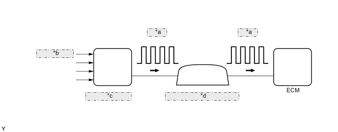
| *a | 4-Pulse |
| *b | from Speed Sensor |
| *c | Skid Control ECU |
| *d | Combination Meter Assembly |
| DTC No. | DTC Detection Condition | Trouble Area |
|---|---|---|
| P050031 | 1. Diagnosis Condition 2. Malfunction Status 3. Malfunction Time 4. Other
|
|
MONITOR DESCRIPTION
The ECM assumes that the vehicle is being driven when the transmission counter gear indicates more than 330 rpm and over 30 seconds have passed since the park/neutral position switch assembly was turned off. If the vehicle speed signal is not input with these conditions satisfied, the ECM concludes that there is a vehicle speed signal malfunction, illuminates the MIL and stores this DTC.
WIRING DIAGRAM
When DTC P050031 is output, a short to ground in the wire harness connected to terminal SPD or an internal short to ground in the relevant ECU is suspected Click here.
CAUTION / NOTICE / HINT
Note
Perform registration and/or initialization when parts related to the automatic transaxle are replaced Click here.
Tech Tips
After performing repair, clear the DTCs and perform the following procedure to check that DTCs are not output.
-
Turn the engine switch on (IG) and wait for 3 seconds or more.
-
Perform the D Position Shift Test inspection in Road Test Click here.
-
Check for DTCs again Click here.
PROCEDURE
-
READ VALUE USING GTS (VEHICLE SPEED)
-
Connect the GTS to the DLC3.
-
Turn the engine switch on (IG).
-
Turn the GTS on.
-
Enter the following menus: Powertrain / Transmission / Data List / Vehicle Speed.
-
Drive the vehicle.
-
Read the value displayed on the GTS.
Result Result Proceed to Values displayed on GTS and speedometer display are not equal A Values displayed on GTS and speedometer display equal B
B 
CHECK FOR INTERMITTENT PROBLEMS Click here
A 
-
-
CHECK HARNESS AND CONNECTOR (COMBINATION METER ASSEMBLY - ECM)
-
Disconnect the H14 combination meter assembly connector.
-
Disconnect the A75 ECM connector.
-
Measure the resistance according to the value(s) in the table below.
Standard Resistance Tester Connection Condition Specified Condition H14-19 (+S) - A75-44 (SPD) Always Below 1 Ω
NG
REPAIR OR REPLACE HARNESS OR CONNECTOR
OK
-
-
CHECK COMBINATION METER SYSTEM
-
Check the circuits that send vehicle speed signals to this system in the combination meter system Click here.
NEXT
-
-
CONFIRM WHETHER MALFUNCTION HAS BEEN SUCCESSFULLY REPAIRED
-
Connect the GTS to the DLC3.
-
Turn the engine switch on (IG).
-
Turn the GTS on.
-
Clear the DTCs Click here.
-
Turn the engine switch off and wait for at least 30 seconds.
-
Start the engine.
-
Turn the GTS on.
-
Drive the vehicle in accordance with the driving pattern described in Confirmation Driving Pattern Click here.
-
Enter the following menus: Powertrain / Transmission / Trouble Codes.
-
Read the DTCs.
Tech Tips
If no DTCs (no pending DTCs) are output, the repair has been successfully completed.
NEXT
END
-