AUTOMATIC TRANSAXLE SYSTEM, Diagnostic DTC:P061512

| DTC Code | DTC Name |
|---|---|
| P061512 | Starter Relay Circuit Short to Battery |
DESCRIPTION
While the engine is being cranked, battery voltage is applied to terminal STA of the ECM.
If the ECM detects the starter control (STA) signal while the vehicle is being driven, it determines that there is a malfunction in the STA circuit. The ECM then illuminates the MIL and stores this DTC.
This monitor runs when the vehicle is driven at 20 km/h (12 mph) or more for 20 seconds.
| DTC No. | DTC Detection Condition | Trouble Area |
|---|---|---|
| P061512 | 1. Diagnosis Condition 2. Malfunction Status 3. Malfunction Time 4. Other
|
|
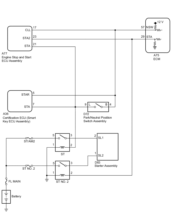
WIRING DIAGRAM
CAUTION / NOTICE / HINT
Note
-
Perform registration and/or initialization when parts related to the automatic transaxle are replaced Click here.
-
Inspect the fuses for circuits related to this system before performing the following inspection procedure.
Tech Tips
-
The following troubleshooting procedure is based on the premise that the engine cranks normally. If the engine does not crank, proceed to the problem symptoms table Click here.
-
Read freeze frame data using the GTS. The ECM records vehicle and driving condition information as freeze frame data the moment a DTC is stored. When troubleshooting, freeze frame data can be helpful in determining whether the vehicle was running or stopped, whether the engine was warmed up or not, whether the air fuel ratio was lean or rich, as well as other data recorded at the time of a malfunction Click here.
-
After performing repair, clear the DTCs and perform the following procedure to check that DTCs are not output.
-
Drive the vehicle for 20 seconds or more under the following conditions:
-
Engine speed is 1000 rpm or more.
-
Vehicle speed is 20 km/h (12 mph) or more.
-
Check for DTCs again Click here.
PROCEDURE
-
READ VALUE USING GTS (STARTER SW)
-
Connect the GTS to the DLC3.
-
Turn the engine switch on (IG).
-
Turn the GTS on.
-
Enter the following menus: Powertrain / Transmission / Data List / Starter SW.
-
According to the display on the GTS, read the Data List.
Standard Condition Starter SW Engine switch on (IG) OFF Driving at 20 km/h (12 mph) or more (engine speed 1000 rpm or more) OFF Tech Tips
-
If the result of either of the above is not as specified, proceed to the next step with the engine switch on (IG), GTS connected and Data List item "Starter SW" selected.
-
If the starter assembly operates continuously when the engine switch is turned on (IG), proceed to the next step without reading the Data List item "Starter SW".
-
OK 
CHECK FOR INTERMITTENT PROBLEMS Click here
NG 
-
-
INSPECT ST NO. 2 RELAY (CHECK FOR SHOT CIRCUIT)
-
Enter the following menus: Powertrain / Transmission / Data List / Starter SW.
-
Remove the ST NO. 2 relay from the engine room relay block and junction block assembly.
-
According to the display on the GTS, read the Data List.
Result Result Proceed to The Data List item "Starter SW" does not change from ON. A The Data List item "Starter SW" changes from ON to OFF. B Tech Tips
-
When the result of the above inspection is "The Data List item "Starter SW" does not change from ON", the ST NO. 2 relay is normal.
-
DTCs may be stored during this inspection. Check for DTCs and clear them using the GTS.
-
B
REPLACE ST NO. 2 RELAY
A
-
-
CHECK TERMINAL VOLTAGE (POWER SOURCE OF ST NO. 2 RELAY)
Tech Tips
The purpose of this step is to check for ST NO. 2 relay terminal voltage under abnormal conditions.
-
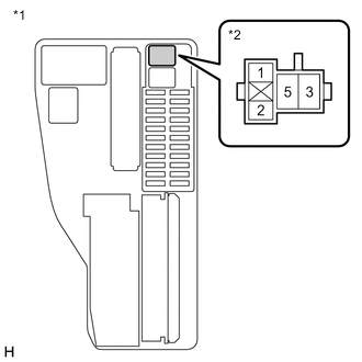
Text in Illustration *1 Engine Room Relay Block and Junction Block Assembly *2 ST NO. 2 Relay Remove the ST NO. 2 relay from the engine room relay block and junction block assembly.
-
Turn the engine switch on (IG).
-
Measure the voltage between ST NO. 2 relay terminal 2 and body ground.
Tech Tips
-
Make a note of the measured voltage as it will be necessary for the inspecting the change in voltage in the next step. As the next step should be conducted under the same conditions, keep the engine switch on (IG) and do not install the ST NO. 2 relay.
-
DTCs may be stored during this inspection. Check for DTCs and clear them using the GTS.
-
If any voltage was measured with the engine switch on (IG), one of the following malfunctions is suspected:
-
Short to +B in the circuit of a connected ECU or the engine switch.
-
Short to +B in the wire harness.
-
NEXT
-
-
INSPECT ENGINE STOP AND START ECU ASSEMBLY (CHECK FOR SHOT CIRCUIT)
-
Text in Illustration *1 Engine Room Relay Block and Junction Block Assembly *2 ST NO. 2 Relay Disconnect the A77 engine stop and start ECU assembly connector.
-
Measure the voltage between ST NO. 2 relay terminal 2 and body ground and compare it to the voltage measured in the previous step.
Result Result Proceed to The voltage between ST NO. 2 relay terminal 2 and body ground does not change when the connector is disconnected. A The voltage between ST NO. 2 relay terminal 2 and body ground changes when the connector is disconnected. B Tech Tips
-
If the voltage is the same before and after disconnecting the connector, the engine stop and start ECU assembly is normal.
-
DTCs may be stored during this inspection. Check for DTCs and clear them using the GTS.
-
B
REPLACE ENGINE STOP AND START ECU ASSEMBLY Click here
A
-
-
INSPECT ECM (CHECK FOR SHOT CIRCUIT)
-
Text in Illustration *1 Engine Room Relay Block and Junction Block Assembly *2 ST NO. 2 Relay Disconnect the A75 ECM connector.
-
Measure the voltage between ST NO. 2 relay terminal 2 and body ground and compare it to the voltage measured in the previous step.
Result Result Proceed to The voltage between ST NO. 2 relay terminal 2 and body ground does not change when the connector is disconnected. A The voltage between ST NO. 2 relay terminal 2 and body ground changes when the connector is disconnected. B Tech Tips
-
If the voltage is the same before and after disconnecting the connector, the ECM is normal.
-
DTCs may be stored during this inspection. Check for DTCs and clear them using the GTS.
-
A
REPAIR OR REPLACE HARNESS OR CONNECTOR (STA SIGNAL CIRCUIT)
B
REPLACE ECM Click here
-