AUTOMATIC TRANSAXLE SYSTEM, Diagnostic DTC:P070312

| DTC Code | DTC Name |
|---|---|
| P070312 | Brake Switch "B" Circuit Short to Battery |
DESCRIPTION
The purpose of this circuit is to prevent the engine from stalling when the brakes are suddenly applied while driving in the lock-up condition.
When the brake pedal is depressed, this switch sends a signal to the ECM. Then the ECM cancels the operation of the lock-up clutch while braking is in progress.
| DTC No. | DTC Detection Condition | Trouble Area |
|---|---|---|
| P070312 | 1. Diagnosis Condition 2. Malfunction Status 3. Malfunction Time 4. Other
|
|
MONITOR DESCRIPTION
This DTC indicates that the stop light switch is remaining on. When the stop light switch remains on during "stop and go" driving, the ECM interprets this as a malfunction of the stop light switch, illuminates the MIL and stores this DTC. The vehicle must STOP (less than 3 km/h (2 mph)) and GO (30 km/h (19 mph) or more) five times for two consecutive driving cycles in order to store this DTC.
WIRING DIAGRAM
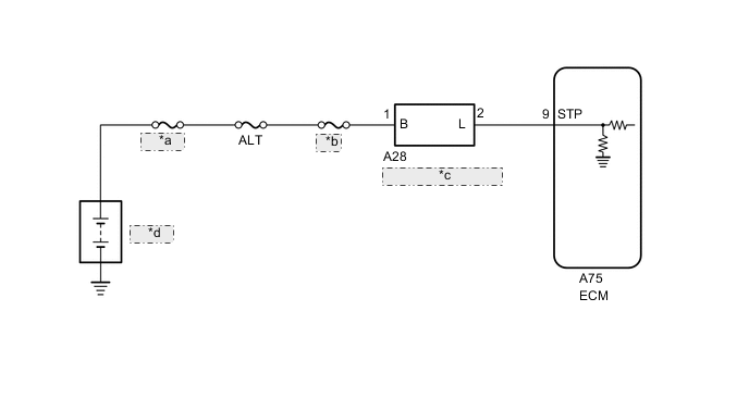
| *a | FL MAIN |
| *b | STOP |
| *c | Stop Light Switch Assembly |
| *d | Battery |
CAUTION / NOTICE / HINT
Note
-
Inspect the fuses for circuits related to this system before performing the following inspection procedure.
-
Perform registration and/or initialization when parts related to the automatic transaxle are replaced Click here.
Tech Tips
After performing repair, clear the DTCs and perform the following procedure to check that DTCs are not output.
-
Repeat above procedure for 5 times:
-
Stop the vehicle (vehicle speed of 3 km/h (2 mph) or less)
-
Drive the vehicle (vehicle speed of 30 km/h (19 mph) or more)
-
Turn the engine switch off.
-
Perform step (1) again.
-
Check for DTCs again Click here.
PROCEDURE
-
READ VALUE USING GTS (STOP LIGHT SW)
-
Connect the GTS to the DLC3.
-
Turn the engine switch on (IG).
-
Turn the GTS on.
-
Enter the following menus: Powertrain / Transmission / Data List / Stop Light SW.
-
Read the Data List according to the display on the GTS.
Transmission Tester Display Measurement Item/Range Normal Condition Diagnostic Note Stop Light SW Stop light switch status/
ON or OFF
-
ON: Brake pedal depressed
-
OFF: Brake pedal released
- Result Result Proceed to Data List value is normal A Data List value is not normal B -
A 
CHECK FOR INTERMITTENT PROBLEMS Click here
B 
-
-
CHECK STOP LIGHT SWITCH ASSEMBLY INSTALLATION
-
Check the stop light switch assembly installation Click here.
OK Stop light switch assembly is installed correctly.
NG
SECURELY REINSTALL STOP LIGHT SWITCH ASSEMBLY Click here
OK
-
-
INSPECT STOP LIGHT SWITCH ASSEMBLY
-
Inspect the stop light switch assembly Click here.
NG
REPLACE STOP LIGHT SWITCH ASSEMBLY Click here
OK
-
-
CHECK TERMINAL VOLTAGE (STP VOLTAGE)
-
Disconnect the A75 ECM connector.
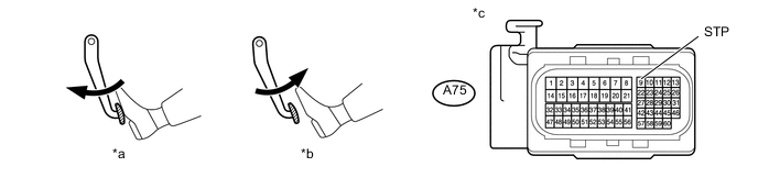
Text in Illustration *a Brake pedal depressed *b Brake pedal released *c Front view of wire harness connector
(to ECM)
- - -
Turn the engine switch on (IG).
-
Measure the voltage according to the value(s) in the table below.
Standard Voltage Tester Connection Condition Specified Condition A75-9 (STP) - Body ground Brake pedal released Below 1.5 V Brake pedal depressed 7.5 to 14 V
OK
REPLACE ECM Click here
NG
REPAIR OR REPLACE HARNESS OR CONNECTOR (STOP LIGHT SWITCH ASSEMBLY - ECM)
-