STOP AND START SYSTEM, Diagnostic DTC:P33B3
| DTC Code | DTC Name |
|---|---|
| P33B3 | External BBC Circuit |
DESCRIPTION
When the engine is started (high electrical load) from engine stopped by the stop and start control, the external backup boost converter (eco run vehicle converter assembly) supplements battery voltage in order to prevent the function from being disabled due to decrease in power source voltage supplied to the navigation system.
After receiving a request from the engine stop and start ECU, the external backup boost converter (eco run vehicle converter assembly) helps maintain the power source voltage if the battery voltage drops due to the high electrical load when the engine is restarted by stop and start control. The DON2 terminal of the external backup boost converter (eco run vehicle converter assembly) receives power supply voltage supplement requests from the engine stop and start ECU and switches from idle mode to supplement mode.
When the engine is started by the stop and start control, if the external backup boost converter (eco run vehicle converter assembly) does not maintain the specified voltage, an error is sent to the engine stop and start ECU. Then, the engine stop and start ECU stores DTC P33B3, and the stop and start cancel indicator blinks.
| DTC No. | DTC Detection Condition | Trouble Area |
|---|---|---|
| P33B3 | Any of the following conditions are met for 1 second or more (1 trip detection logic):
|
|
CONFIRMATION DRIVING PATTERN
Tech Tips
DTCs for the stop and start system are not cleared even if the malfunction has been repaired. After repairing the malfunction, be sure to clear the DTCs Click here.
-
CONFIRMATION AFTER TROUBLESHOOTING
Tech Tips
-
If the cable is disconnected from the negative (-) battery terminal, stop and start control is prohibited until refresh charge is completed. In this case, drive the vehicle approximately 5 to 60 minutes until refresh charge is completed and stop and start control operation is permitted.
-
Allow the engine to idle for 3 minutes after it is warmed up and check that the engine idle speed is within 50 rpm of the target idle speed.
-
Connect the GTS to the DLC3.
-
Turn the engine switch on (IG) and turn the GTS on.
-
Clear the DTCs Click here.
-
Start the engine and warm it up.
-
Drive the vehicle at 7 km/h (4.3 mph) or more.
CAUTION:
When performing Confirmation Driving Pattern, obey all speed limits and traffic laws.
-
Depress the brake pedal and stop the vehicle.
-
Keep the engine stopped by stop and start control for 1 second or more. (Keep the shift lever in D.)
-
Release the brake pedal with the shift lever in D to start the engine.
Tech Tips
If the engine cranks slowly when the engine is restarted, it can be determined that the battery voltage is low.
-
Check that DTCs are not output Click here.
-
-
STOP AND START SYSTEM OPERATION CHECK
Tech Tips
If the cable is disconnected from the negative (-) battery terminal, stop and start control is prohibited until refresh charge is completed. In this case, drive the vehicle approximately 5 to 60 minutes until refresh charge is completed and stop and start control operation is permitted.
-
Start the engine and warm it up.
-
Turn the air conditioning system off.
-
Drive the vehicle at 7 km/h (4.3 mph) or more.
CAUTION:
When performing Confirmation Driving Pattern, obey all speed limits and traffic laws.
-
Depress the brake pedal and stop the vehicle.
-
Allow the engine to stop by stop and start control. (Keep the shift lever in D.)
-
Release the brake pedal with the shift lever in D to start the engine.
-
WIRING DIAGRAM
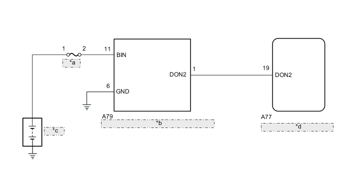
| *a | BBC_PA |
| *b | External Backup Boost Converter (Eco Run Vehicle Converter Assembly) |
| *c | Battery |
| *d | Engine Stop and Start ECU |
CAUTION / NOTICE / HINT
Note
Inspect the fuses for circuits related to this system before performing the following procedure.
PROCEDURE
-
CONFIRM FREEZE FRAME DATA (STATE OF EXTERNAL BBC)
Note
Clearing the DTC will also clear the freeze frame data, so before clearing be sure to record the freeze frame data.
-
Following the display on the GTS, check the freeze frame data and read "State of External BBC" in the freeze frame data when P33B3 was output.
Result GTS Display Proceed to
-
Duty Err
-
Cycle Err
A Low Vol B Over Vol C -
A 
REPLACE EXTERNAL BACKUP BOOST CONVERTER (ECO RUN VEHICLE CONVERTER ASSEMBLY) Click here
C 
CHECK HARNESS AND CONNECTOR (ENGINE STOP AND START ECU - EXTERNAL BACKUP BOOST CONVERTER ASSEMBLY) Click here
B 
-
-
CHECK CONNECTOR (EXTERNAL BACKUP BOOST CONVERTER (ECO RUN VEHICLE CONVERTER ASSEMBLY))
-
Check if the connector of the external backup boost converter (eco run vehicle converter assembly) is connected securely.
OK The connector is securely connected.
NG
CONNECT CONNECTOR CORRECTLY
OK
-
-
CHECK HARNESS AND CONNECTOR (ENGINE STOP AND START ECU - EXTERNAL BACKUP BOOST CONVERTER ASSEMBLY)
-
Disconnect the A77 engine stop and start ECU connector.
-
Disconnect the A79 external backup boost converter (eco run vehicle converter assembly) connector.
-
Measure the resistance according to the value(s) in the table below.
Standard Resistance Tester Connection Condition Specified Condition A77-19 (DON2) - A79-1 (DON2) Always Below 1 Ω A77-19 (DON2) - Body ground Always 10 kΩ or higher A79-1 (DON2) - Body ground Always 10 kΩ or higher
NG
REPAIR OR REPLACE HARNESS OR CONNECTOR
OK
-
-
CHECK HARNESS AND CONNECTOR (EXTERNAL BACKUP BOOST CONVERTER (ECO RUN VEHICLE CONVERTER ASSEMBLY) - BBC_PA FUSE)
-
Disconnect the A79 external backup boost converter (eco run vehicle converter assembly) connector.
-
Remove the BBC_PA fuse from engine room relay block and junction block.
-
Measure the resistance according to the value(s) in the table below.
Standard Resistance Tester Connection Condition Specified Condition A79-11(BIN) - BBC_PA fuse terminal 2 Always Below 1 Ω A79-11(BIN) - Body ground Always 10 kΩ or higher BBC_PA fuse terminal 2 - Body ground Always 10 kΩ or higher
OK
REPLACE EXTERNAL BACKUP BOOST CONVERTER (ECO RUN VEHICLE CONVERTER ASSEMBLY) Click here
NG
REPAIR OR REPLACE HARNESS OR CONNECTOR
-