LANE DEPARTURE ALERT SYSTEM(w/ Steering Control) Indicator Circuit
DESCRIPTION
When the forward recognition camera detects a lane departure alert main switch signal, it sends the signal to the combination meter assembly via CAN communication. Then the lane departure alert indicator turns on.
WIRING DIAGRAM
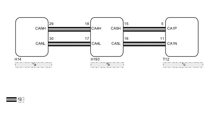
| *a | Combination Meter Assembly |
| *b | Central Gateway ECU |
| *c | Forward Recognition Camera |
| *d | CAN Communication Line |
PROCEDURE
-
READ VALUE USING GTS (CAN BUS CHECK)
-
Connect the GTS to the DLC3.
-
Turn the engine switch on (IG).
-
Turn the GTS on.
-
Enter the following menus: System Select / Can Bus Check.
Result Result Proceed to All of the ECUs and sensors that are currently connected to the CAN communication system are displayed. A None of the ECUs and sensors that are currently connected to the CAN communication system are displayed, or some of them are not displayed. B -
Turn the engine switch off.
B 
GO TO CAN COMMUNICATION SYSTEM Click here
A 
-
-
CHECK FOR DTCs (HEALTH CHECK)
-
Connect the GTS to the DLC3.
-
Turn the engine switch on (IG).
-
Turn the GTS on.
-
Enter the following menus: System Select / Health Check.
-
Check DTCs.
Result Result Proceed to No DTCs are output. A DTCs are output. B -
Turn the engine switch off.
B
GO TO DTC CHART
A
-
-
PERFORM ACTIVE TEST USING GTS (METER DISPLAY 1)
-
Connect the GTS to the DLC3.
-
Turn the engine switch on (IG).
-
Turn the GTS on.
-
Enter the following menus: Body Electrical / Combination Meter / Active Test.
-
According to the display on the GTS, perform the Active Test.
Combination Meter Tester Display Test Part Control Range Diagnostic Note Meter Display 1 Multi-information display OFF or All - Result Result Proceed to The multi-information display in the combination meter assembly turns on or off according to the operation of the Active Test. A The multi-information display in the combination meter assembly does not turn on or off according to the operation of the Active Test. B -
Turn the engine switch off.
B
GO TO METER / GAUGE SYSTEM Click here
A
-
-
READ VALUE USING GTS
-
Connect the GTS to the DLC3.
-
Turn the engine switch on (IG).
-
Turn the GTS on.
-
Enter the following menus: Chassis / LKA/LDA / Data List.
-
Read the Data List according to the display on the GTS.
LKA/LDA Tester Display Test Part Control Range Diagnostic Note LDA Control Control status of lane departure alert system (w/ Steering Control)/ Prohibit or Permit Prohibit: Control prohibited
Permit: Control permitted
- Result Result Proceed to The lane departure alert indicator illuminates and turns on according to the operation of the lane departure alert main switch A The lane departure alert indicator does not illuminate but the Data List item LDA Control changes according to the operation of the lane departure alert main switch B The lane departure alert indicator does not illuminate and the Data List item LDA Control does not change according to the operation of the lane departure alert main switch C
A
PROCEED TO NEXT SUSPECTED AREA SHOWN IN PROBLEM SYMPTOMS TABLE Click here
B
REPLACE COMBINATION METER ASSEMBLY Click here
C
REPLACE FORWARD RECOGNITION CAMERA Click here
-