LANE DEPARTURE ALERT SYSTEM(w/ Steering Control), Diagnostic DTC:U0235, U1104
| DTC Code | DTC Name |
|---|---|
| U0235 | Lost Communication with Cruise Control Front Distance Range Sensor |
| U1104 | Lost Communication with Driving Support ECU |
DESCRIPTION
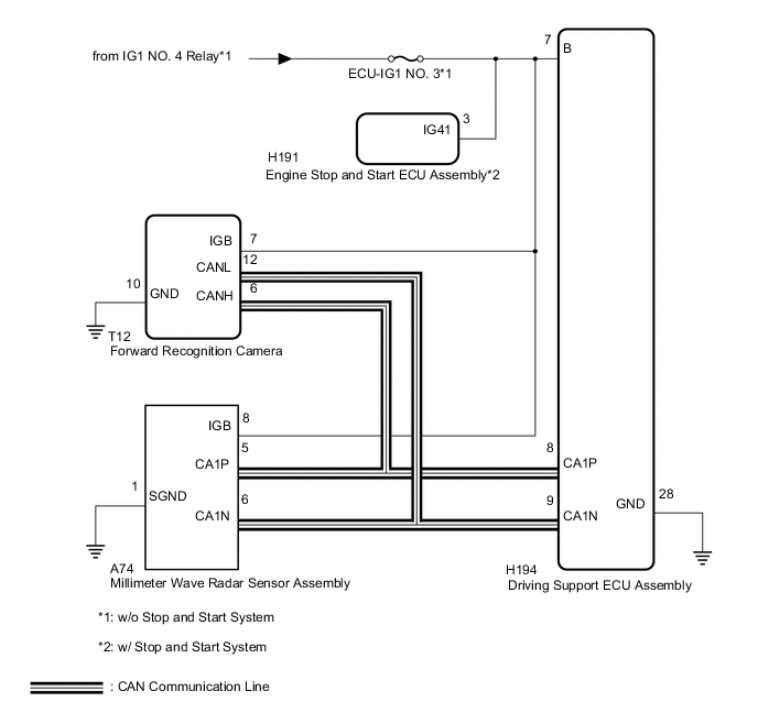
The forward recognition camera communicates with the driving support ECU assembly and millimeter wave radar sensor assembly via CAN communication. If there is a communication error with the driving support ECU assembly or millimeter wave radar sensor assembly, the forward recognition camera stores DTC U0235 or U1104.
| DTC No. | DTC Detection Condition | Trouble Area |
|---|---|---|
| U0235 | When the engine switch is on (IG), a communication error between the millimeter wave radar sensor assembly and the forward recognition camera is detected for approximately 1 second. |
|
| U1104 | When the engine switch is on (IG), a communication error between the driving support ECU assembly and the forward recognition camera is detected for approximately 1 second. |
|
WIRING DIAGRAM
CAUTION / NOTICE / HINT
Note
-
Inspect the fuses for circuits related to this system before performing the following procedure.
-
When replacing the driving support ECU assembly, always replace it with a new one. If a driving support ECU assembly which was installed to another vehicle is used, the information stored in the driving support ECU assembly will not match the information from the vehicle. As a result, a DTC may be stored.
-
When the forward recognition camera is replaced with a new one, adjustment of the Recognition Camera/Target Position Memory and Recognition Camera Axis Adjust must be performed Click here.
-
When the millimeter wave radar sensor assembly is replaced with a new one, adjustment of the radar sensor beam axis must be performed Click here.
PROCEDURE
-
CHECK DTC OUTPUT (PRE-CRASH SAFETY SYSTEM)
-
Connect the GTS to the DLC3.
-
Turn the engine switch on (IG).
-
Turn the GTS on.
-
Enter the following menus: Body Electrical / Pre-Crash 2 / Trouble Codes.
-
Check for DTCs Click here.
Result Result Proceed to DTC U1002 is not output A DTC U1002 is output B -
Turn the engine switch off.
B 
GO TO CAN COMMUNICATION SYSTEM Click here
A 
-
-
CHECK FOR SHORT IN SUB BUS LINE
-
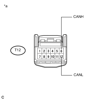
Text in Illustration *a Front view of wire harness connector
(to Forward Recognition Camera)
Disconnect the T12 forward recognition camera connector.
-
Measure the resistance according to the value(s) in the table below.
Standard Resistance Tester Connection Condition Specified Condition T12-6 (CANH) - T12-12 (CANL) Cable disconnected from negative (-) battery terminal 54 to 69 Ω
NG
REPAIR OR REPLACE HARNESS OR CONNECTOR (CAN BUS LINE)
OK
-
-
CHECK DTC OUTPUT (LANE DEPARTURE ALERT SYSTEM)
-
Connect the GTS to the DLC3.
-
Turn the engine switch on (IG).
-
Turn the GTS on.
-
Enter the following menus: Chassis / LKA/LDA / Trouble Codes.
-
Check for DTCs Click here.
Result Result Proceed to DTC U0235 and U1104 are output A Only DTC U1104 is output B Only DTC U0235 is output C
B 
CHECK POWER SOURCE CIRCUIT (DRIVING SUPPORT ECU ASSEMBLY) Click here
C
CHECK POWER SOURCE CIRCUIT (MILLIMETER WAVE RADAR SENSOR ASSEMBLY) Click here
A
-
-
CHECK POWER SOURCE CIRCUIT (DRIVING SUPPORT ECU ASSEMBLY)
-
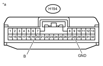
Text in Illustration *a Front view of wire harness connector
(to Driving Support ECU Assembly)
Disconnect the H194 driving support ECU assembly connector.
-
Turn the engine switch on (IG).
-
Measure the voltage according to the value(s) in the table below.
Standard Voltage Tester Connection Condition Specified Condition H194-7 (B) - Body ground Engine switch on (IG) 11 to 14 V -
Turn the engine switch off.
-
Measure the resistance according to the value(s) in the table below.
Standard Resistance Tester Connection Condition Specified Condition H194-28 (GND) - Body ground Always Below 1 Ω Result Result Proceed to OK A NG (w/o Stop and Start System) B NG (w/ Stop and Start System) C -
Reconnect the H194 driving support ECU assembly connector.
B
REPAIR OR REPLACE HARNESS OR CONNECTOR (POWER SOURCE CIRCUIT)
C
GO TO STOP AND START SYSTEM Click here
A
-
-
CHECK POWER SOURCE CIRCUIT (MILLIMETER WAVE RADAR SENSOR ASSEMBLY)
-
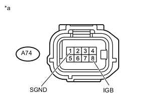
Text in Illustration *a Front view of wire harness connector
(to Millimeter Wave Radar Sensor Assembly)
Disconnect the A74 millimeter wave radar sensor assembly connector.
-
Turn the engine switch on (IG).
-
Measure the voltage according to the value(s) in the table below.
Standard Voltage Tester Connection Condition Specified Condition A74-8 (IGB) - Body ground Engine switch on (IG) 11 to 14 V -
Turn the engine switch off.
-
Measure the resistance according to the value(s) in the table below.
Standard Resistance Tester Connection Condition Specified Condition A74-1 (SGND) - Body ground Always Below 1 Ω Result Result Proceed to OK A NG (w/o Stop and Start System) B NG (w/ Stop and Start System) C
A
REPLACE FORWARD RECOGNITION CAMERA
B
REPAIR OR REPLACE HARNESS OR CONNECTOR (POWER SOURCE CIRCUIT)
C
GO TO STOP AND START SYSTEM Click here
-
-
CHECK POWER SOURCE CIRCUIT (DRIVING SUPPORT ECU ASSEMBLY)
-
Text in Illustration *a Front view of wire harness connector
(to Driving Support ECU Assembly)
Disconnect the H194 driving support ECU assembly connector.
-
Turn the engine switch on (IG).
-
Measure the voltage according to the value(s) in the table below.
Standard Voltage Tester Connection Condition Specified Condition H194-7 (B) - Body ground Engine switch on (IG) 11 to 14 V -
Turn the engine switch off.
-
Measure the resistance according to the value(s) in the table below.
Standard Resistance Tester Connection Condition Specified Condition H194-28 (GND) - Body ground Always Below 1 Ω Result Result Proceed to OK A NG (w/o Stop and Start System) B NG (w/ Stop and Start System) C -
Reconnect the H194 driving support ECU assembly connector.
B
REPAIR OR REPLACE HARNESS OR CONNECTOR (POWER SOURCE CIRCUIT)
C
GO TO STOP AND START SYSTEM Click here
A
-
-
REPLACE DRIVING SUPPORT ECU ASSEMBLY
-
Replace the driving support ECU assembly Click here.
NEXT
-
-
CHECK DTC OUTPUT (LANE DEPARTURE ALERT SYSTEM)
-
Connect the GTS to the DLC3.
-
Turn the engine switch on (IG).
-
Turn the GTS on.
-
Enter the following menus: Chassis / LKA/LDA / Trouble Codes.
-
Clear the DTCs Click here.
-
Make sure that the DTC detection conditions are met.
Tech Tips
If the detection conditions are not met, the system cannot detect the malfunction.
-
Check for DTCs Click here.
Result Result Proceed to DTC U1104 is not output A DTC U1104 is output B
A
END (DRIVING SUPPORT ECU ASSEMBLY WAS DEFECTIVE)
B
REPLACE FORWARD RECOGNITION CAMERA Click here
-
-
CHECK POWER SOURCE CIRCUIT (MILLIMETER WAVE RADAR SENSOR ASSEMBLY)
-
Text in Illustration *a Front view of wire harness connector
(to Millimeter Wave Radar Sensor Assembly)
Disconnect the A74 millimeter wave radar sensor assembly connector.
-
Turn the engine switch on (IG).
-
Measure the voltage according to the value(s) in the table below.
Standard Voltage Tester Connection Condition Specified Condition A74-8 (IGB) - Body ground Engine switch on (IG) 11 to 14 V -
Turn the engine switch off.
-
Measure the resistance according to the value(s) in the table below.
Standard Resistance Tester Connection Condition Specified Condition A74-1 (SGND) - Body ground Always Below 1 Ω Result Result Proceed to OK A NG (w/o Stop and Start System) B NG (w/ Stop and Start System) C
B
REPAIR OR REPLACE HARNESS OR CONNECTOR (POWER SOURCE CIRCUIT)
C
GO TO STOP AND START SYSTEM Click here
A
-
-
REPLACE MILLIMETER WAVE RADAR SENSOR ASSEMBLY
-
Replace the millimeter wave radar sensor assembly Click here.
-
Adjust the millimeter wave radar sensor assembly Click here.
NEXT
-
-
CHECK DTC OUTPUT (LANE DEPARTURE ALERT SYSTEM)
-
Connect the GTS to the DLC3.
-
Turn the engine switch on (IG).
-
Turn the GTS on.
-
Enter the following menus: Chassis / LKA/LDA / Trouble Codes.
-
Clear the DTCs Click here.
-
Make sure that the DTC detection conditions are met.
Tech Tips
If the detection conditions are not met, the system cannot detect the malfunction.
-
Check for DTCs Click here.
Result Result Proceed to DTC U0235 is not output A DTC U0235 is output B
A
END (MILLIMETER WAVE RADAR SENSOR ASSEMBLY WAS DEFECTIVE)
B
REPLACE FORWARD RECOGNITION CAMERA Click here
-