DYNAMIC RADAR CRUISE CONTROL SYSTEM(for 2GR-FE, 2AR-FE) Distance Control Switch Circuit
DESCRIPTION
The vehicle-to-vehicle distance control switch is used to set the distance for vehicle-to-vehicle distance control mode. The vehicle-to-vehicle distance control switch is installed in the steering pad switch assembly. The vehicle-to-vehicle distance set value can be changed by operating the vehicle-to-vehicle distance control switch (steering pad switch assembly) while the dynamic radar cruise control system is controlling vehicle speed in vehicle-to-vehicle distance control mode.
WIRING DIAGRAM
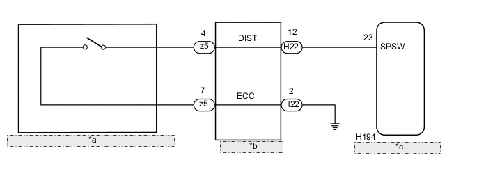
| *a | Vehicle-to-vehicle Distance Control Switch (Steering Pad Switch Assembly) |
| *b | Spiral Cable Sub-assembly |
| *c | Driving Support ECU Assembly |
PROCEDURE
-
READ VALUE USING GTS (DISTANCE CONTROL SWITCH)
-
Connect the GTS to the DLC3.
-
Turn the engine switch on (IG).
-
Turn the GTS on.
-
Enter the following menus: Powertrain / Radar Cruise2 / Data List.
-
Check the Data List to confirm function of the distance control switch.
Radar Cruise2 Tester Display Measurement Item/Range Normal Condition Diagnostic Note Distance Control Switch Vehicle-to-vehicle distance control switch status / ON or OFF ON: Vehicle-to-vehicle distance control switch pushed
OFF: Vehicle-to-vehicle distance control switch not pushed
- OK The display changes in accordance with switch operation. -
Turn the engine switch off.
OK 
PROCEED TO NEXT SUSPECTED AREA SHOWN IN PROBLEM SYMPTOMS TABLE Click here
NG 
-
-
INSPECT STEERING PAD SWITCH ASSEMBLY
-
Remove the steering pad switch assembly Click here.
-
Inspect the steering pad switch assembly Click here.
-
Reinstall the steering pad switch assembly Click here.
NG
REPLACE STEERING PAD SWITCH ASSEMBLY Click here
OK
-
-
INSPECT SPIRAL CABLE SUB-ASSEMBLY
-
Remove the spiral cable sub-assembly Click here.
-
Inspect the spiral cable sub-assembly Click here.
-
Reinstall the spiral cable sub-assembly Click here.
NG
REPLACE SPIRAL CABLE SUB-ASSEMBLY Click here
OK
-
-
CHECK HARNESS AND CONNECTOR (SPIRAL CABLE SUB-ASSEMBLY - DRIVING SUPPORT ECU ASSEMBLY)
-
Disconnect the H22 spiral cable sub-assembly connector.
-
Disconnect the H194 driving support ECU assembly connector.
-
Measure the resistance according to the value(s) in the table below.
Standard Resistance (Check for Open) Tester Connection Condition Specified Condition H22-12 (DIST) - H194-23 (SPSW) Always Below 1 Ω Standard Resistance (Check for Short) Tester Connection Condition Specified Condition H22-12 (DIST) or H194-23 (SPSW) - Body ground Always 10 kΩ or higher -
Reconnect the H194 driving support ECU assembly connector.
-
Reconnect the H22 spiral cable sub-assembly connector.
NG
REPAIR OR REPLACE HARNESS OR CONNECTOR
OK
-
-
CHECK HARNESS AND CONNECTOR (SPIRAL CABLE SUB-ASSEMBLY - BODY GROUND)
-
Disconnect the H22 spiral cable sub-assembly connector.
-
Measure the resistance according to the value(s) in the table below.
Standard Resistance (Check for Open) Tester Connection Condition Specified Condition H22-2 (ECC) - Body ground Always Below 1 Ω -
Reconnect the H22 spiral cable sub-assembly connector.
OK
REPLACE DRIVING SUPPORT ECU ASSEMBLY Click here
NG
REPAIR OR REPLACE HARNESS OR CONNECTOR
-