CRUISE CONTROL SYSTEM(for 2GR-FE, 2AR-FE) TERMINALS OF ECM
-
CHECK ECM (for 2GR-FE)

Terminal No. (Symbols) Wiring Color Terminal Description Condition Specified Condition A22-51 (STP) - D23-49 (E1) BE - BR Stop light signal Engine switch on (IG), Brake pedal depressed 11 to 14 V A22-51 (STP) - D23-49 (E1) BE - BR Stop light signal Engine switch on (IG), Brake pedal released Below 1 V A22-47 (CCS) - D23-49 (E1) W - BR Cruise control switch circuit Cruise control main switch (ON/OFF button) OFF 1 MΩ or higher A22-47 (CCS) - D23-49 (E1) W - BR Cruise control switch circuit Cruise control main switch (ON/OFF button) ON Below 2.5 Ω A22-47 (CCS) - D23-49 (E1) W - BR Cruise control switch circuit +/RES switch ON 235 to 245 Ω A22-47 (CCS) - D23-49 (E1) W - BR Cruise control switch circuit -/SET switch ON 617 to 643 Ω A22-47 (CCS) - D23-49 (E1) W - BR Cruise control switch circuit CANCEL switch ON 1509 to 1571 Ω A22-36 (ST1-) - D23-49 (E1) GR - BR Stop light signal Engine switch on (IG), Brake pedal depressed Below 1 V A22-36 (ST1-) - D23-49 (E1) GR - BR Stop light signal Engine switch on (IG),
Brake pedal released
11 to 14 V D23-69 (D) - D23-49 (E1) G - BR D shift position signal Engine switch on (IG),
Shift lever D or S position
11 to 14 V D23-69 (D) - D23-49 (E1) G - BR D shift position signal Engine switch on (IG),
Shift lever except D or S position
Below 1 V A22-50 (SFTD) - D23-49 (E1) L - BR Down shift switch signal Engine switch on (IG) and shift lever S position 11 to 14 V A22-50 (SFTD) - D23-49 (E1) L - BR Down shift switch signal Engine switch on (IG) and shift lever "-" position (Down shift) Below 1 V A22-34 (SFTU) - D23-49 (E1) R - BR Up shift switch signal Engine switch on (IG) and shift lever S position 11 to 14 V A22-34 (SFTU) - D23-49 (E1) R - BR Up shift switch signal Engine switch on (IG) and shift lever "+" position (Up shift) Below 1 V -
CHECK ECM (for 2AR-FE)
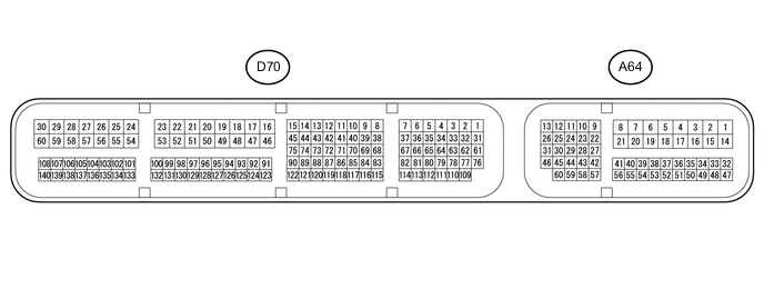
Terminal No. (Symbols) Wiring Color Terminal Description Condition Specified Condition A64-11 (STP) - D70-16 (E1) BE - BR Stop light signal Engine switch on (IG), Brake pedal depressed 11 to 14 V A64-11 (STP) - D70-16 (E1) BE - BR Stop light signal Engine switch on (IG), Brake pedal released Below 1 V A64-40 (CCS) - D70-16 (E1) W - BR Cruise control switch circuit Cruise control main switch (ON/OFF button) OFF 1 MΩ or higher A64-40 (CCS) - D70-16 (E1) W - BR Cruise control switch circuit Cruise control main switch (ON/OFF button) ON Below 2.5 Ω A64-40 (CCS) - D70-16 (E1) W - BR Cruise control switch circuit +/RES switch ON 235 to 245 Ω A64-40 (CCS) - D70-16 (E1) W - BR Cruise control switch circuit -/SET switch ON 617 to 643 Ω A64-40 (CCS) - D70-16 (E1) W - BR Cruise control switch circuit CANCEL switch ON 1509 to 1571 Ω A64-24 (ST1-) - D70-16 (E1) GR - BR Stop light signal Engine switch on (IG), Brake pedal depressed Below 1 V A64-24 (ST1-) - D70-16 (E1) GR - BR Stop light signal Engine switch on (IG),
Brake pedal released
11 to 14 V D70-67 (D) - D70-16 (E1) G - BR D shift position signal Engine switch on (IG),
Shift lever D or S position
11 to 14 V D70-67 (D) - D70-16 (E1) G - BR D shift position signal Engine switch on (IG),
Shift lever except D or S position
Below 1 V A64-43 (SFTD) - D70-16 (E1) L - BR Down shift switch signal Engine switch on (IG) and shift lever S position 11 to 14 V A64-43 (SFTD) - D70-16 (E1) L - BR Down shift switch signal Engine switch on (IG) and shift lever "-" position (Down shift) Below 1 V A64-42 (SFTU) - D70-16 (E1) R - BR Up shift switch signal Engine switch on (IG) and shift lever S position 11 to 14 V A64-42 (SFTU) - D70-16 (E1) R - BR Up shift switch signal Engine switch on (IG) and shift lever "+" position (Up shift) Below 1 V