OIL PUMP REMOVAL

PROCEDURE
-
REMOVE AUTOMATIC TRANSAXLE ASSEMBLY
-
REMOVE DRIVE PLATE AND RING GEAR SUB-ASSEMBLY
-
INSTALL ENGINE TO ENGINE STAND
-
REMOVE ENGINE HANGERS
-
REMOVE INTAKE AIR SURGE TANK ASSEMBLY
-
REMOVE NO. 1 SURGE TANK STAY
-
REMOVE THROTTLE BODY BRACKET
-
REMOVE IGNITION COIL ASSEMBLY
-
REMOVE EXHAUST MANIFOLD SUB-ASSEMBLY RH
-
REMOVE NO. 2 ENGINE OIL LEVEL DIPSTICK GUIDE
-
REMOVE NO. 2 MANIFOLD STAY
-
REMOVE NO. 2 EXHAUST MANIFOLD HEAT INSULATOR
-
REMOVE EXHAUST MANIFOLD SUB-ASSEMBLY LH
-
REMOVE V-RIBBED BELT TENSIONER ASSEMBLY
-
SEPARATE OIL COOLER PIPE (w/ Oil Cooler)
-
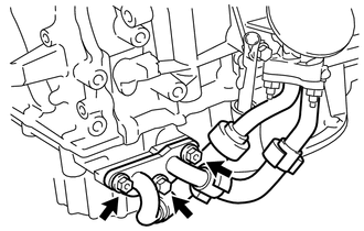
Remove the bolt and 2 nuts, and disconnect the oil cooler pipe from the oil pan sub-assembly.
-
Remove the gasket from the oil pan sub-assembly.
-
-
REMOVE ENGINE OIL LEVEL DIPSTICK GUIDE
-
REMOVE NO. 2 TIMING GEAR COVER
-
REMOVE WATER PUMP PULLEY
-
REMOVE NO. 2 IDLER PULLEY SUB-ASSEMBLY
-
REMOVE NO. 1 VACUUM SWITCHING VALVE
-
REMOVE CRANK POSITION SENSOR
-
REMOVE NO. 1 OIL PIPE
-
REMOVE OIL PIPE
-
REMOVE CRANKSHAFT PULLEY
-
REMOVE NO. 1 FRONT ENGINE MOUNTING BRACKET LH
-
REMOVE WATER INLET HOUSING
-
REMOVE CYLINDER HEAD COVER SUB-ASSEMBLY
-
REMOVE CYLINDER HEAD COVER SUB-ASSEMBLY LH
-
REMOVE NO. 2 OIL PAN SUB-ASSEMBLY
-
REMOVE OIL STRAINER SUB-ASSEMBLY
-
REMOVE OIL PAN SUB-ASSEMBLY
-
REMOVE TIMING CHAIN COVER SUB-ASSEMBLY
-
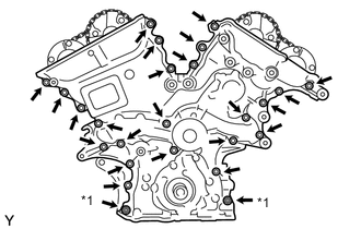
Text in Illustration *1 Nut Remove the 23 bolts and 2 nuts shown in the illustration.
-
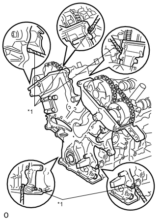
Text in Illustration *1 Protective Tape Remove the timing chain cover sub-assembly by prying between the timing chain cover sub-assembly and cylinder head or cylinder block with a screwdriver.
Note
Be careful not to damage the contact surfaces of the cylinder head, cylinder block and timing chain cover sub-assembly.
Tech Tips
Tape the screwdriver tip before use.
-
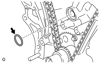
Remove the gasket.
-
-
REMOVE TIMING CHAIN CASE OIL SEAL
-
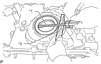
Text in Illustration *1 Protective Tape *2 Wooden Block Using a screwdriver and wooden block, pry out the timing chain case oil seal.
Tech Tips
Tape the screwdriver tip before use.
-