OIL PUMP INSTALLATION

PROCEDURE
-
INSTALL TIMING CHAIN CASE OIL SEAL
-
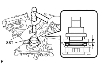
Using SST, tap in a new timing chain case oil seal until its surface is flush with the timing chain cover sub-assembly edge.
- SST
- 09223-22010
- 09506-35010
Note
-
Keep the lip free from foreign matter.
-
Do not tap on the timing chain case oil seal at an angle.
-
Make sure that the timing chain case oil seal edge does not stick out of the timing chain cover sub-assembly.
Tech Tips
Tap in the timing chain case oil seal so that it is positioned within 1.0 mm from the edge of the timing chain cover sub-assembly.
-
Apply a light coat of MP grease to the timing chain cover oil seal lip.
-
-
INSTALL TIMING CHAIN COVER SUB-ASSEMBLY
-
Apply seal packing in a continuous line to the engine unit as shown in the following illustration.
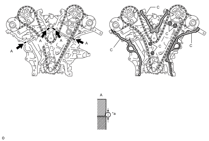
Text in Illustration *a Seal Packing Diameter: 3.0 mm (0.118 in.) or more 
Seal Packing Seal packing Toyota Genuine Seal Packing Black, Three Bond 1207B or equivalent Seal diameter 3.0 mm (0.118 in.) Note
-
Be sure to clean and degrease the contact surfaces, especially the surfaces indicated by C in the illustration.
-
If there is oil on the contact surfaces, wipe them with an oil-free cloth before applying seal packing.
-
Install the timing chain cover sub-assembly within 3 minutes.
-
Do not start the engine for at least 2 hours after installing.
-
-
Apply seal packing in a continuous line to the timing chain cover sub-assembly as shown in the following illustration.
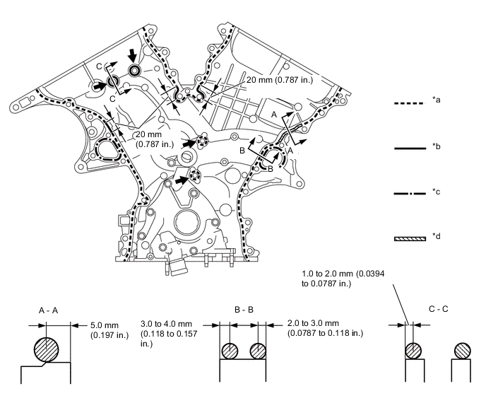
Text in Illustration *a Dashed Line Area
(Seal packing: Toyota Genuine Seal Packing Black, Three Bond 1207B or equivalent)
*b Continuous Line Area
(Seal packing: Toyota Genuine Seal Packing Black, Three Bond 1207B or equivalent)
*c Alternate Long and Short Dashed Line Area
(Seal packing: Toyota Genuine Seal Packing 1282B, Three Bond 1282B or equivalent)
*d Diagonal Line Area
(Seal packing: Toyota Genuine Seal Packing Black, Three Bond 1207B or equivalent)
Be sure to apply seal packing - - Seal packing Toyota Genuine Seal Packing Black, Three Bond 1207B or equivalent Toyota Genuine Seal Packing 1282B, Three Bond 1282B or equivalent Note
-
If there is oil on the contact surfaces, wipe them with an oil-free cloth before applying seal packing.
-
Install the timing chain cover sub-assembly within 3 minutes and tighten the bolts within 15 minutes after applying seal packing.
-
Do not start the engine for at least 2 hours after installing.
Seal Packing Application Chart Area Seal Packing Diameter Application Position from Inside Seal Line Continuous Line Area 4.5 mm or more (0.177 in.) 1.0 to 2.0 mm (0.0394 to 0.0787 in.) Alternate Long and Short Dashed Line Area 3.5 mm or more (0.138 in.) 2.0 to 3.0 mm (0.0787 to 0.118 in.) Dashed Line Area 3.5 mm or more (0.138 in.) 3.0 to 4.0 mm (0.118 to 0.157 in.) Diagonal Line Area 6.0 mm or more (0.236 in.) 5.0 mm (0.197 in.) -
-
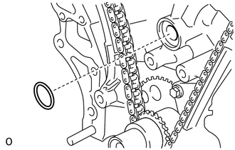
Install a new gasket.
-
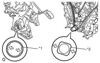
Text in Illustration *1 Drive Rotor Spline *2 Crankshaft Align the drive rotor spline and the crankshaft as shown in the illustration. Install the spline and timing chain cover sub-assembly to the crankshaft.
-
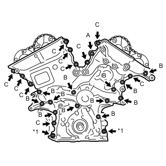
Text in Illustration *1 Nut Temporarily tighten the timing chain cover sub-assembly with the 23 bolts and 2 nuts.
Bolt Length Item Length Bolt A 40 mm (1.57 in.) Bolt B 55 mm (2.17 in.) Bolt C 28 mm (1.102 in.) Note
Make sure that there is no oil on the threads of bolt B and C.
-
Fully tighten the bolts in Area 1.
-
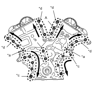
Text in Illustration *a Area 1 *b Area 2 *c Area 3 *d Area 4 Fully tighten the bolts in Area 2.
- Torque:
- 21 N*m { 214 kgf*cm, 15 ft.*lbf }
-
Fully tighten the bolts and nuts in Area 3.
- Torque:
- 21 N*m { 214 kgf*cm, 15 ft.*lbf }
Tech Tips
Tighten the bolts and nuts from top to bottom as shown in the illustration.
-
Fully tighten the bolts in Area 4.
- Torque:
- Bolt A
- 43 N*m { 438 kgf*cm, 32 ft.*lbf }
- Torque:
- Except bolt A
- 21 N*m { 214 kgf*cm, 15 ft.*lbf }
Tech Tips
Tighten the bolts from bottom to top as shown in the illustration.
-
-
INSTALL OIL PAN SUB-ASSEMBLY
-
INSTALL OIL STRAINER SUB-ASSEMBLY
-
INSTALL NO. 2 OIL PAN SUB-ASSEMBLY
-
INSTALL CYLINDER HEAD COVER SUB-ASSEMBLY
-
INSTALL CYLINDER HEAD COVER SUB-ASSEMBLY LH
-
INSTALL WATER INLET HOUSING
-
INSTALL NO. 1 FRONT ENGINE MOUNTING BRACKET LH
-
INSTALL CRANKSHAFT PULLEY
-
INSTALL NO. 1 OIL PIPE
-
INSTALL OIL PIPE
-
INSTALL CRANK POSITION SENSOR
-
INSTALL NO. 1 VACUUM SWITCHING VALVE
-
INSTALL WATER PUMP PULLEY
-
INSTALL NO. 2 IDLER PULLEY SUB-ASSEMBLY
-
INSTALL NO. 2 TIMING GEAR COVER
-
INSTALL ENGINE OIL LEVEL DIPSTICK GUIDE
-
INSTALL OIL COOLER PIPE (w/ Oil Cooler)
-
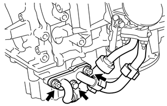
Install a new gasket to the oil pan sub-assembly.
-
Install the oil cooler pipe with the bolt and 2 nuts.
- Torque:
- 21 N*m { 214 kgf*cm, 15 ft.*lbf }
-
-
INSTALL V-RIBBED BELT TENSIONER ASSEMBLY
-
INSTALL EXHAUST MANIFOLD SUB-ASSEMBLY LH
-
INSTALL NO. 2 EXHAUST MANIFOLD HEAT INSULATOR
-
INSTALL NO. 2 MANIFOLD STAY
-
INSTALL NO. 2 ENGINE OIL LEVEL DIPSTICK GUIDE
-
INSTALL EXHAUST MANIFOLD SUB-ASSEMBLY RH
-
INSTALL IGNITION COIL ASSEMBLY
-
INSTALL THROTTLE BODY BRACKET
-
INSTALL NO. 1 SURGE TANK STAY
-
INSTALL INTAKE AIR SURGE TANK ASSEMBLY
-
INSTALL ENGINE HANGERS
-
REMOVE ENGINE STAND
-
INSTALL DRIVE PLATE AND RING GEAR SUB-ASSEMBLY
-
INSTALL AUTOMATIC TRANSAXLE ASSEMBLY