COOLING FAN SYSTEM Cooling Fan Circuit
DESCRIPTION
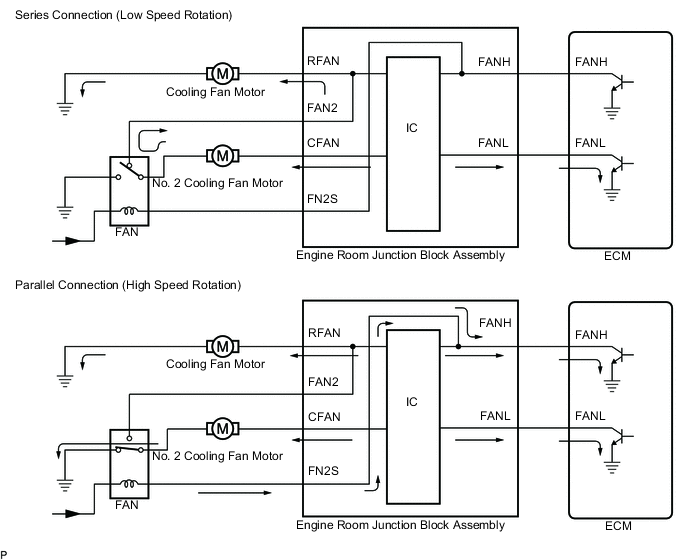
The ECM monitors engine coolant temperature, the air conditioning switch, the air conditioning refrigerant pressure and engine speed. It also sends the FANL and FANH signals to the engine room junction block assembly to operate the cooling fan motor and No. 2 cooling fan motor.
The ECM switches the cooling fan motor and No. 2 cooling fan motor circuits from a series (low speed rotation) to parallel (high speed rotation) connection by changing the FANH signal, thereby controlling the 2 levels of fan speed.
| Input signal | FANL | OFF | ON | ON |
| FANH | OFF | OFF | ON | |
| Condition | Cooling fan motor | OFF | ON (Series connection (Low speed rotation)) | ON (Parallel connection (High speed rotation)) |
| No. 2 cooling fan motor | OFF | ON (Series connection (Low speed rotation)) | ON (Parallel connection (High speed rotation)) |
WIRING DIAGRAM
CAUTION / NOTICE / HINT
Note
Inspect the fuses for circuits related to this system before performing the following inspection procedure.
PROCEDURE
-
PERFORM ACTIVE TEST USING GTS (CONTROL THE ELECTRIC COOLING FAN)
Tech Tips
If cooling fan speed does not change, proceed to the next step.
-
Connect the GTS to the DLC3.
-
Turn the engine switch on (IG).
-
Turn the GTS on.
-
Enter the following menus: Powertrain / Engine and ECT / Active Test / Control the Electric Cooling Fan.
-
Check the operation of the cooling fans using the GTS.
OK GTS Operation Fan Operation ON Cooling fan operates OFF Cooling fan stops Result Result Proceed to NG A OK B
B 
INSPECT ENGINE ROOM JUNCTION BLOCK ASSEMBLY (SIGNAL READING CHECK) Click here
A 
-
-
CHECK HARNESS AND CONNECTOR (ECM - ENGINE ROOM JUNCTION BLOCK ASSEMBLY)
-
Disconnect the A64 ECM connector.
-
Remove the engine room junction block assembly from the engine room relay block and junction block assembly.
-
Disconnect the 1F engine room junction block assembly connector.
-
Measure the resistance according to the value(s) in the table below.
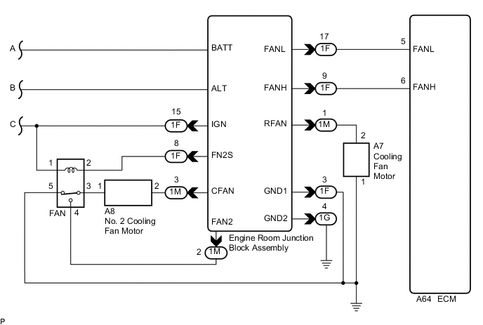
Standard Resistance Tester Connection Condition Specified Condition A64-5 (FANL) - 1F-17 (FANL) Always Below 1 Ω A64-6 (FANH) - 1F-9 (FANH) Always Below 1 Ω A64-5 (FANL) or 1F-17 (FANL) - Body ground Always 10 kΩ or higher A64-6 (FANH) or 1F-9 (FANH) - Body ground Always 10 kΩ or higher
NG 
REPAIR OR REPLACE HARNESS OR CONNECTOR (ECM - ENGINE ROOM JUNCTION BLOCK ASSEMBLY)
OK
-
-
INSPECT ENGINE ROOM JUNCTION BLOCK ASSEMBLY (SIGNAL READING CHECK)
-
Using a voltmeter, check the signal reading of the engine room junction block assembly Click here.
OK Output signal reading is normal.
NG
INSPECT ENGINE ROOM JUNCTION BLOCK ASSEMBLY (RESULTS OF SIGNAL READING CHECK) Click here
OK
-
-
CHECK HARNESS AND CONNECTOR (ENGINE ROOM JUNCTION BLOCK ASSEMBLY POWER SOURCE)
-
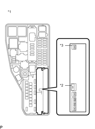
Text in Illustration *1 Engine Room Relay Block and Junction Block Assembly *2 ALT *3 BATT Remove the engine room junction block assembly from the engine room relay block and junction block assembly.
-
Measure the voltage according to the value(s) in the table below.
Standard Voltage Tester Connection Condition Specified Condition (BATT) - Body ground Engine switch off 11 to 14 V (ALT) - Body ground Engine switch off 11 to 14 V
NG
REPAIR OR REPLACE HARNESS OR CONNECTOR (ENGINE ROOM JUNCTION BLOCK ASSEMBLY - BATTERY)
OK
-
-
CHECK HARNESS AND CONNECTOR (ENGINE ROOM JUNCTION BLOCK ASSEMBLY - BODY GROUND)
-
Remove the engine room junction block assembly from the engine room relay block and junction block assembly.
-
Disconnect the 1F and 1G engine room junction block assembly connectors.
-
Measure the resistance according to the value(s) in the table below.
Standard Resistance Tester Connection Condition Specified Condition 1F-3 (GND1) - Body ground Always Below 1 Ω 1G-4 (GND2) - Body ground Always Below 1 Ω Tech Tips
Make sure that there are no short circuits to the battery.
NG
REPAIR OR REPLACE HARNESS OR CONNECTOR (ENGINE ROOM JUNCTION BLOCK ASSEMBLY - BODY GROUND)
OK
-
-
CHECK HARNESS AND CONNECTOR (FAN RELAY POWER SOURCE)
-
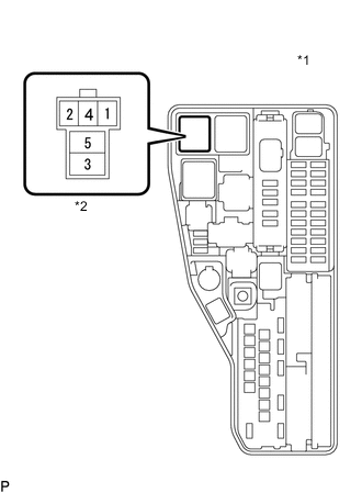
Text in Illustration *1 Engine Room Relay Block and Junction Block Assembly *2 FAN Relay Remove the FAN relay from the engine room relay block and junction block assembly.
-
Turn the engine switch on (IG).
-
Measure the voltage according to the value(s) in the table below.
Standard Voltage Tester Connection Condition Specified Condition 1 (FAN relay) - Body ground Engine switch on (IG) 11 to 14 V
NG
CHECK HARNESS AND CONNECTOR (FAN RELAY - INSTRUMENT PANEL JUNCTION BLOCK ASSEMBLY) Click here
OK
-
-
CHECK HARNESS AND CONNECTOR (FAN RELAY - ENGINE ROOM JUNCTION BLOCK ASSEMBLY)
-
Remove the FAN relay from the engine room relay block and junction block assembly.
-
Remove the engine room junction block assembly from the engine room relay block and junction block assembly.
-
Disconnect the 1F engine room junction block assembly connector.
-
Disconnect the 3D instrument panel junction block assembly connector.
-
Measure the resistance according to the value(s) in the table below.
Standard Resistance Tester Connection Condition Specified Condition 1 (FAN relay) - 1F-15 (IGN) Always Below 1 Ω 1 (FAN relay) or 1F-15 (IGN) - Body ground Always 10 kΩ or higher Tech Tips
Make sure that there are no short circuits to the battery.
NG
REPAIR OR REPLACE HARNESS OR CONNECTOR (ENGINE ROOM JUNCTION BLOCK ASSEMBLY - INSTRUMENT PANEL JUNCTION BLOCK ASSEMBLY)
OK
-
-
INSPECT RELAY (FAN RELAY)
-
Inspect the FAN relay Click here.
NG
REPLACE RELAY (FAN RELAY)
OK
-
-
CHECK HARNESS AND CONNECTOR (FAN RELAY - ENGINE ROOM JUNCTION BLOCK ASSEMBLY)
-
Remove the FAN relay from the engine room relay block and junction block assembly.
-
Remove the engine room junction block assembly from the engine room relay block and junction block assembly.
-
Disconnect the 1F engine room junction block assembly connector.
-
Measure the resistance according to the value(s) in the table below.
Standard Resistance Tester Connection Condition Specified Condition 2 (FAN relay) - 1F-8 (FN2S) Always Below 1 Ω 2 (FAN relay) or 1F-8 (FN2S) - Body ground Always 10 kΩ or higher Tech Tips
Make sure that there are no short circuits to the battery.
NG
REPAIR OR REPLACE HARNESS OR CONNECTOR (FAN RELAY - ENGINE ROOM JUNCTION BLOCK ASSEMBLY)
OK
-
-
CHECK HARNESS AND CONNECTOR (FAN RELAY - ENGINE ROOM JUNCTION BLOCK ASSEMBLY)
-
Remove the FAN relay from the engine room relay block and junction block assembly.
-
Remove the engine room junction block assembly from the engine room relay block and junction block assembly.
-
Measure the resistance according to the value(s) in the table below.
Standard Resistance Tester Connection Condition Specified Condition 4 (FAN relay) - 1M-2 (FAN2) Always Below 1 Ω 4 (FAN relay) or 1M-2 (FAN2) - Body ground Always 10 kΩ or higher Tech Tips
Make sure that there are no short circuits to the battery.
NG
REPAIR OR REPLACE HARNESS OR CONNECTOR (FAN RELAY - ENGINE ROOM JUNCTION BLOCK ASSEMBLY)
OK
-
-
CHECK HARNESS AND CONNECTOR (FAN RELAY - BODY GROUND)
-
Remove the FAN relay from the engine room relay block and junction block assembly.
-
Measure the resistance according to the value(s) in the table below.
Standard Resistance Tester Connection Condition Specified Condition 5 (FAN relay) - Body ground Always Below 1 Ω Tech Tips
Make sure that there are no short circuits to the battery.
NG
REPAIR OR REPLACE HARNESS OR CONNECTOR (FAN RELAY - BODY GROUND)
OK
-
-
INSPECT NO. 2 COOLING FAN MOTOR
-
Inspect the No. 2 cooling fan motor Click here.
NG
REPLACE NO. 2 COOLING FAN MOTOR Click here
OK
-
-
CHECK HARNESS AND CONNECTOR (FAN RELAY - NO. 2 COOLING FAN MOTOR)
-
Remove the FAN relay from the engine room relay block and junction block assembly.
-
Disconnect the A8 No. 2 cooling fan motor connector.
-
Measure the resistance according to the value(s) in the table below.
Standard Resistance Tester Connection Condition Specified Condition 3 (FAN relay) - A8-1 Always Below 1 Ω 3 (FAN relay) or A8-1 - Body ground Always 10 kΩ or higher Tech Tips
Make sure that there are no short circuits to the battery.
NG
REPAIR OR REPLACE HARNESS OR CONNECTOR (FAN RELAY - NO. 2 COOLING FAN MOTOR)
OK
-
-
CHECK HARNESS AND CONNECTOR (NO. 2 COOLING FAN MOTOR - ENGINE ROOM JUNCTION BLOCK ASSEMBLY)
-
Disconnect the A8 No. 2 cooling fan motor connector.
-
Remove the engine room junction block assembly from the engine room relay block and junction block assembly.
-
Measure the resistance according to the value(s) in the table below.
Standard Resistance Tester Connection Condition Specified Condition A8-2 - 1M-3 (CFAN) Always Below 1 Ω A8-2 or 1M-3 (CFAN) - Body ground Always 10 kΩ or higher Tech Tips
Make sure that there are no short circuits to the battery.
NG
REPAIR OR REPLACE HARNESS OR CONNECTOR (NO. 2 COOLING FAN MOTOR - ENGINE ROOM JUNCTION BLOCK ASSEMBLY)
OK
-
-
INSPECT COOLING FAN MOTOR
-
Inspect the cooling fan motor Click here.
NG
REPLACE COOLING FAN MOTOR Click here
OK
-
-
CHECK HARNESS AND CONNECTOR (COOLING FAN MOTOR - ENGINE ROOM JUNCTION BLOCK ASSEMBLY)
-
Disconnect the A7 cooling fan motor connector.
-
Remove the engine room junction block assembly from the engine room relay block and junction block assembly.
-
Measure the resistance according to the value(s) in the table below.
Standard Resistance Tester Connection Condition Specified Condition A7-2 - 1M-1 (RFAN) Always Below 1 Ω A7-2 or 1M-1 (RFAN) - Body ground Always 10 kΩ or higher Tech Tips
Make sure that there are no short circuits to the battery.
NG
REPAIR OR REPLACE HARNESS OR CONNECTOR (COOLING FAN MOTOR - ENGINE ROOM JUNCTION BLOCK ASSEMBLY)
OK
-
-
CHECK HARNESS AND CONNECTOR (COOLING FAN MOTOR - BODY GROUND)
-
Disconnect the A7 cooling fan motor connector.
-
Measure the resistance according to the value(s) in the table below.
Standard Resistance Tester Connection Condition Specified Condition A7-1 - Body ground Always Below 1 Ω Tech Tips
Make sure that there are no short circuits to the battery.
OK
PROCEED TO NEXT SUSPECTED AREA SHOWN IN PROBLEM SYMPTOMS TABLE Click here
NG
REPAIR OR REPLACE HARNESS OR CONNECTOR (COOLING FAN MOTOR - BODY GROUND)
-
-
CHECK HARNESS AND CONNECTOR (FAN RELAY - INSTRUMENT PANEL JUNCTION BLOCK ASSEMBLY)
-
Remove the FAN relay from the engine room relay block and junction block assembly.
-
Disconnect the 3D instrument panel junction block assembly connector.
-
Remove the engine room junction block assembly from the engine room relay block and junction block assembly.
-
Disconnect the 1F engine room junction block assembly connector.
-
Measure the resistance according to the value(s) in the table below.
Standard Resistance Tester Connection Condition Specified Condition 1 (FAN relay) - 3D-36 Always Below 1 Ω 1 (FAN relay) or 3D-36 - Body ground Always 10 kΩ or higher Tech Tips
Make sure that there are no short circuits to the battery.
NG
REPAIR OR REPLACE HARNESS OR CONNECTOR (FAN RELAY - INSTRUMENT PANEL JUNCTION BLOCK ASSEMBLY)
OK
-
-
INSPECT INSTRUMENT PANEL JUNCTION BLOCK ASSEMBLY (IG1 NO. 2 RELAY)
-
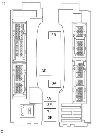
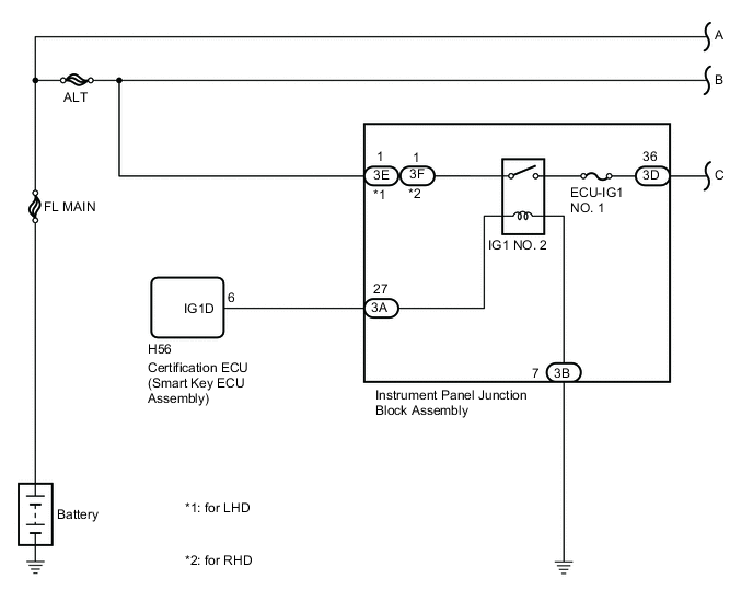
Text in Illustration *A for LHD *B for RHD *1 Instrument Panel Junction Block Assembly Disconnect the 3D and 3E or 3F instrument panel junction block assembly connectors.
-
Measure the resistance according to the value(s) in the table below.
Standard Resistance (for LHD) Tester Connection Condition Specified Condition 3D-36 - 3E-1 Battery voltage is not applied between terminals 3A-27 and 3B-7 10 kΩ or higher 3D-36 - 3E-1 Battery voltage is applied between terminals 3A-27 and 3B-7 Below 1 Ω Standard Resistance (for RHD) Tester Connection Condition Specified Condition 3D-36 - 3F-1 Battery voltage is not applied between terminals 3A-27 and 3B-7 10 kΩ or higher 3D-36 - 3F-1 Battery voltage is applied between terminals 3A-27 and 3B-7 Below 1 Ω
NG
REPLACE INSTRUMENT PANEL JUNCTION BLOCK ASSEMBLY (IG1 NO. 2 RELAY)
OK
-
-
CHECK HARNESS AND CONNECTOR (INSTRUMENT PANEL JUNCTION BLOCK ASSEMBLY POWER SOURCE)
-
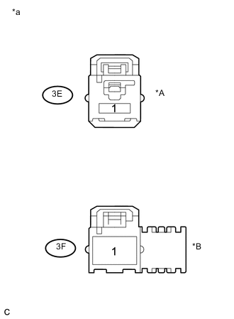
Text in Illustration *A for LHD *B for RHD *a Front view of wire harness connector
(to Instrument Panel Junction Block Assembly)
Disconnect the 3E or 3F instrument panel junction block assembly connector.
-
Measure the voltage according to the value(s) in the table below.
Standard voltage (for LHD) Tester Connection Condition Specified Condition 3E-1 - Body ground Always 11 to 14 V Standard voltage (for RHD) Tester Connection Condition Specified Condition 3F-1 - Body ground Always 11 to 14 V
NG
REPAIR OR REPLACE HARNESS OR CONNECTOR (INSTRUMENT PANEL JUNCTION BLOCK ASSEMBLY - BATTERY)
OK
-
-
CHECK HARNESS AND CONNECTOR (INSTRUMENT PANEL JUNCTION BLOCK ASSEMBLY - BODY GROUND)
-
Disconnect the 3B instrument panel junction block assembly connector.
-
Measure the resistance according to the value(s) in the table below.
Standard Resistance Tester Connection Condition Specified Condition 3B-7 - Body ground Always Below 1 Ω Tech Tips
Make sure that there are no short circuits to the battery.
NG
REPAIR OR REPLACE HARNESS OR CONNECTOR (INSTRUMENT PANEL JUNCTION BLOCK ASSEMBLY - BODY GROUND)
OK
-
-
CHECK HARNESS AND CONNECTOR (INSTRUMENT PANEL JUNCTION BLOCK ASSEMBLY - CERTIFICATION ECU (SMART KEY ECU ASSEMBLY))
-
Disconnect the 3A instrument panel junction block assembly connector.
-
Disconnect the H56 certification ECU (smart key ECU assembly) connector.
-
Measure the resistance according to the value(s) in the table below.
Standard Resistance Tester Connection Condition Specified Condition 3A-27 - H56-6 (IG1D) Always Below 1 Ω 3A-27 or H56-6 (IG1D) - Body ground Always 10 kΩ or higher Tech Tips
Make sure that there are no short circuits to the battery.
OK
CHECK SMART ENTRY AND START SYSTEM Click here
NG
REPAIR OR REPLACE HARNESS OR CONNECTOR (INSTRUMENT PANEL JUNCTION BLOCK ASSEMBLY - CERTIFICATION ECU (SMART KEY ECU ASSEMBLY))
-