EXHAUST MANIFOLD INSTALLATION
PROCEDURE
-
INSTALL EXHAUST MANIFOLD SUB-ASSEMBLY LH
-
Set a new gasket to the cylinder head sub-assembly.
-
Temporarily install the exhaust manifold sub-assembly LH with the 6 nuts.
-
Temporarily install the No. 2 manifold stay with the bolt and nut.
-
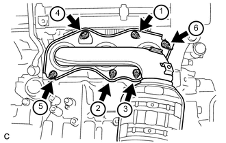
Using a 12 mm deep socket wrench, in several steps, uniformly tighten the 6 nuts in the order shown in the illustration.
- Torque:
- 21 N*m { 214 kgf*cm, 15 ft.*lbf }
-
-
INSTALL NO. 2 MANIFOLD STAY
-
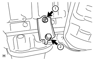
Tighten the bolt and nut in the order shown in the illustration.
- Torque:
- 34 N*m { 347 kgf*cm, 25 ft.*lbf }
-
-
INSTALL NO. 2 EXHAUST MANIFOLD HEAT INSULATOR
-
Install the No. 2 exhaust manifold heat insulator with the 3 bolts.
- Torque:
- 8.5 N*m { 87 kgf*cm, 75 in.*lbf }
-
-
INSTALL NO. 2 ENGINE OIL LEVEL DIPSTICK GUIDE
-
INSTALL AIR FUEL RATIO SENSOR (for Bank 2)
-
INSTALL EXHAUST MANIFOLD SUB-ASSEMBLY RH
-
Set a new gasket to the cylinder head sub-assembly.
-
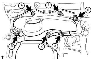
Using a 12 mm deep socket wrench, install the exhaust manifold sub-assembly RH by tightening the 6 nuts in the order shown in the illustration.
- Torque:
- 21 N*m { 214 kgf*cm, 15 ft.*lbf }
-
-
INSTALL AIR FUEL RATIO SENSOR (for Bank 1)
-
INSTALL FRONT EXHAUST PIPE ASSEMBLY
-
Install 3 new gaskets to the front exhaust pipe assembly.
-
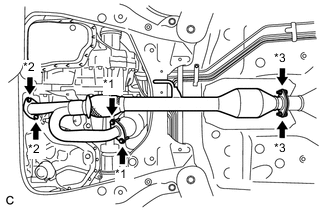
Text in Illustration *1 Bolt *2 Nut *3 Bolt and Nut Install the front exhaust pipe assembly with the 4 bolts and 4 nuts.
- Torque:
- Bolt
- 55 N*m { 561 kgf*cm, 41 ft.*lbf }
- Nut
- 55 N*m { 561 kgf*cm, 41 ft.*lbf }
- Bolt and Nut
- 49 N*m { 500 kgf*cm, 36 ft.*lbf }
-
Install the No. 1 exhaust pipe support bracket with the 2 bolts (for Rear Side).
- Torque:
- 33 N*m { 337 kgf*cm, 24 ft.*lbf }
-
Connect the 2 heated oxygen sensor connectors.
-
Install the 2 wire harnesses to the clamp.
-
-
INSTALL NO. 1 EXHAUST PIPE SUPPORT BRACKET (for Front Side)
-
INSTALL RADIATOR RESERVE TANK ASSEMBLY
-
INSTALL ENGINE UNDER COVER RH (w/ Front Lower Bumper Absorber)
-
INSTALL ENGINE UNDER COVER RH (w/o Front Lower Bumper Absorber)
-
INSTALL FRONT WHEEL OPENING EXTENSION PAD RH
-
INSPECT FOR EXHAUST GAS LEAK