FUEL PRESSURE SENSOR INSPECTION
PROCEDURE
-
INSPECT FUEL PRESSURE SENSOR
Note
-
Do not remove the fuel pressure sensor from the fuel delivery pipe sub-assembly.
-
If the fuel pressure sensor is removed, replace the fuel delivery pipe sub-assembly (fuel pressure sensor) with a new one.
-
Check the fuel pressure sensor output voltage.
-
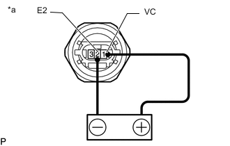
Text in Illustration *a Component without harness connected
(Fuel Pressure Sensor)
*b Voltage applied between terminals Apply 5 V between terminals 1 (VC) and 2 (E2).
Note
-
Be careful when connecting the leads as the fuel pressure sensor may be damaged if the leads are connected to the wrong terminals.
-
Do not apply more than 6 V to terminals 1 (VC) and 2 (E2).
Tech Tips
If a stable power supply is not available, connect 4 nickel-metal hydride batteries (1.2 V each) or equivalent in series.
-
-
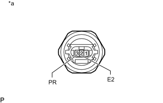
Text in Illustration *a Component without harness connected
(Fuel Pressure Sensor)
Measure the voltage between terminals.
Standard Voltage: Tester Connection Condition Specified Condition 3 (PR) - 2 (E2) Pressure not applied to fuel pressure sensor Approximately
0.4 to 0.6 V*
*: The output voltage changes depending on the voltage applied to the terminals. If the result is not as specified, replace the fuel delivery pipe sub-assembly (fuel pressure sensor).
-
-