EGR VALVE INSTALLATION
PROCEDURE
-
INSTALL EGR VALVE ASSEMBLY
Tech Tips
After replacing the EGR valve assembly, perform the Inspection After Repairs Click here.
-
Install a new EGR valve gasket to the EGR valve assembly.
-
Install the EGR valve assembly to the EGR cooler assembly with the 2 nuts.
- Torque:
- 25 N*m { 255 kgf*cm, 18 ft.*lbf }
-
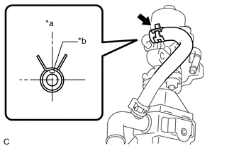
Text in Illustration *a Upper
(When the EGR valve assembly is installed on the engine assembly)
*b Paint Mark Connect the No. 1 water by-pass hose to the EGR valve assembly and slide the clip to secure it.
Tech Tips
Make sure the direction of the clip is as shown in the illustration.
-
-
INSTALL EGR VALVE WITH COOLER ASSEMBLY
-
Install a new No. 2 EGR pipe gasket to the EGR valve assembly.
-
Install a new EGR cooler gasket to the EGR pipe connector.
-
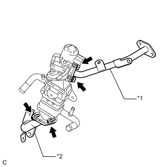
Text in Illustration *1 No. 2 EGR Pipe *2 EGR Pipe Connector Temporarily connect the No. 2 EGR pipe to the EGR valve assembly with the 2 bolts.
-
Temporarily connect the EGR pipe connector to the EGR cooler assembly with the 2 bolts.
-
Install a new EGR cooler gasket to the EGR pipe connector.
-
Install a new EGR inlet gasket to the intake manifold.
-
Temporarily install the EGR valve with cooler assembly, No. 2 EGR pipe and EGR pipe connector to the cylinder head sub-assembly, cylinder block sub-assembly, intake manifold and exhaust manifold converter sub-assembly (TWC: Front Catalyst) with the 4 bolts and 3 nuts.
-
Tighten the 8 bolts and 3 nuts in the order shown in the illustration.
Text in Illustration *a Bolt (A) *b Bolt (B) *c Bolt (C) *d Nut (A) *e Nut (B) - - 
Bolt 
Nut - Torque:
- Bolt (A) and Nut (B)
- 36 N*m { 367 kgf*cm, 27 ft.*lbf }
- Bolt (B)
- 25 N*m { 255 kgf*cm, 18 ft.*lbf }
- Bolt (C)
- 10 N*m { 102 kgf*cm, 7 ft.*lbf }
- Nut (A)
- 21 N*m { 214 kgf*cm, 15 ft.*lbf }
-
Engage the 2 wire harness clamps to the No. 2 EGR pipe.
-
Temporarily install the 2 EGR valve brackets with the 4 bolts.
-
Tighten the 4 bolts in the order shown in the illustration.
- Torque:
- 21 N*m { 214 kgf*cm, 15 ft.*lbf }
-
Install the fuel hose bracket to the EGR valve bracket with the engine cover joint.
- Torque:
- 13 N*m { 133 kgf*cm, 10 ft.*lbf }
-
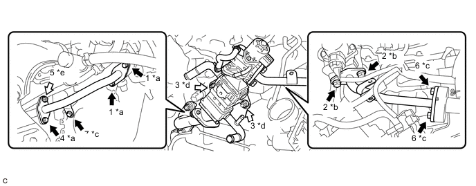
Connect the No. 4 water by-pass hose to the EGR cooler assembly and slide the clip to secure it.
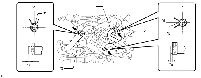
Text in Illustration *1 No. 2 Water By-pass Hose *2 No. 3 Water By-pass Hose *3 No. 4 Water By-pass Hose - - *a 1 to 6 mm (0.0394 to 0.236 in.) *b Paint Mark *c Upper *d Left Tech Tips
Make sure the direction of the clip is as shown in the illustration.
-
Connect the No. 3 water by-pass hose to the EGR cooler assembly and slide the clip to secure it.
Tech Tips
Make sure the direction of the clip is as shown in the illustration.
-
Connect the No. 2 water by-pass hose to the EGR valve assembly and slide the clip to secure it.
Tech Tips
Make sure the direction of the clip is as shown in the illustration.
-
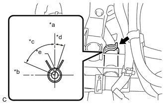
Text in Illustration *a Upper *b Front *c 75° *d 15° *b Paint Mark Connect the water hose sub-assembly to the EGR cooler assembly and slide the clip to secure it.
Tech Tips
Engage the clip within the area shown in the illustration.
-
Engage the water hose to the hose clamp.
-
Connect the EGR valve assembly connector.
-
-
CONNECT ENGINE WIRE
-
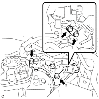
Connect the engine coolant temperature sensor connector.
-
Install the bolt.
- Torque:
- 8.0 N*m { 82 kgf*cm, 71 in.*lbf }
-
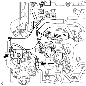
Text in Illustration *a Fuel Pump Sub-assembly Connector *b Ignition Coil Assembly Connector *c Camshaft Position Sensor Connector Bolt Nut 
Connector Engage the clamp.
-
Connect the fuel pump sub-assembly connector.
-
Connect the ignition coil assembly connector.
-
Connect the 2 camshaft position sensor connectors.
-
Install the nut.
- Torque:
- 8.0 N*m { 82 kgf*cm, 71 in.*lbf }
-
Connect the 2 earth wires to the EGR valve bracket with the 2 bolts.
- Torque:
- 8.0 N*m { 82 kgf*cm, 71 in.*lbf }
-
-
INSTALL FUEL PUMP PROTECTOR
-
INSTALL AIR CLEANER CASE SUB-ASSEMBLY
-
INSTALL AIR CLEANER FILTER ELEMENT SUB-ASSEMBLY
-
INSTALL AIR CLEANER CAP WITH AIR CLEANER HOSE
-
ADD ENGINE COOLANT (for Engine)
-
INSPECT FOR COOLANT LEAK (for Engine)
-
INSPECT FOR EXHAUST GAS LEAK
-
INSTALL NO. 1 ENGINE COVER SUB-ASSEMBLY
-
PERFORM INITIALIZATION
-
Perform Inspection After Repair after replacing the EGR valve assembly Click here.
-