CYLINDER HEAD GASKET REMOVAL

PROCEDURE
-
REMOVE CAMSHAFT
-
REMOVE NO. 2 CAMSHAFT
-
REMOVE CAMSHAFT HOUSING SUB-ASSEMBLY RH
-
REMOVE CAMSHAFT TIMING GEAR ASSEMBLY AND NO. 2 CHAIN SUB-ASSEMBLY (for Bank 2)
-
REMOVE NO. 3 CHAIN TENSIONER ASSEMBLY
-
REMOVE CAMSHAFT BEARING CAP (for Bank 2)
-
REMOVE NO. 3 CAMSHAFT
-
REMOVE NO. 4 CAMSHAFT
-
REMOVE CAMSHAFT HOUSING SUB-ASSEMBLY LH
-
REMOVE NO. 1 VALVE ROCKER ARM SUB-ASSEMBLY
-
Remove the 24 No. 1 valve rocker arm assemblies.
Tech Tips
Arrange the removed parts in the correct order.
-
-
REMOVE VALVE LASH ADJUSTER ASSEMBLY
-
Remove the 24 valve lash adjuster assemblies from the cylinder head sub-assembly.
Tech Tips
Arrange the removed parts in the correct order.
-
-
REMOVE VALVE STEM CAP
-
Remove the 24 valve stem caps.
-
-
REMOVE WATER OUTLET
-
REMOVE CYLINDER HEAD SUB-ASSEMBLY RH
-
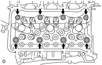
Using a 10 mm bi-hexagon wrench, uniformly loosen the 8 cylinder head set bolts in the sequence shown in the illustration. Remove the 8 cylinder head set bolts and plate washers.
Note
-
Be careful not to drop washers into the cylinder head sub-assembly RH.
-
Cylinder head sub-assembly RH warpage or cracking could result from removing bolts in the incorrect order.
Tech Tips
Arrange the removed parts in the correct order.
-
-
Remove the cylinder head sub-assembly RH.
-
-
REMOVE CYLINDER HEAD GASKET RH
-
Remove the cylinder head gasket RH.
-
-
REMOVE CYLINDER HEAD SUB-ASSEMBLY LH
-
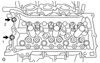
Uniformly loosen and remove the 2 cylinder head set bolts in several steps and in the sequence shown in the illustration.
-
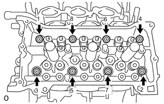
Using a 10 mm bi-hexagon wrench, uniformly loosen the 8 bolts in the sequence shown in the illustration. Remove the 8 cylinder head set bolts and plate washers.
Note
-
Be careful not to drop washers into the cylinder head sub-assembly LH.
-
Cylinder head sub-assembly LH warpage or cracking could result from removing bolts in the incorrect order.
Tech Tips
Be sure to keep separate the removed parts for each installation position.
-
-
Remove the cylinder head sub-assembly LH.
-
-
REMOVE CYLINDER HEAD GASKET LH
-
Remove the cylinder head gasket LH.
-