CAMSHAFT INSTALLATION

CAUTION / NOTICE / HINT
Tech Tips
Perform "Inspection After Repair" after replacing the camshaft, No. 2 camshaft, camshaft timing gear assembly or camshaft timing exhaust gear assembly Click here.
PROCEDURE
-
INSTALL NO. 2 CAMSHAFT BEARING
-
INSTALL NO. 1 CAMSHAFT BEARING
-
INSTALL OIL CONTROL VALVE FILTER
-
INSTALL CAMSHAFT TIMING EXHAUST GEAR ASSEMBLY
-
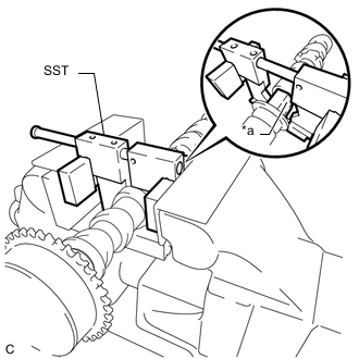
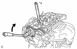
Text in Illustration *a Hexagonal Portion Using SST, grip the hexagonal portion, and then secure the SST and No. 2 camshaft in a vise as shown in the illustration.
- SST
- 09212-31010
Note
-
Do not damage the No. 2 camshaft.
-
Never grip areas other than the hexagonal portion, as this may cause damage.
-
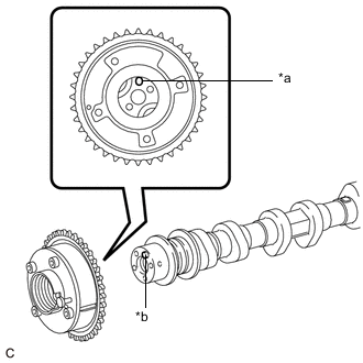
Text in Illustration *a Knock Pin Hole *b Knock Pin Align and fit the knock pin of the No. 2 camshaft with the knock pin hole of the camshaft timing exhaust gear assembly.
Note
Be careful not to damage the contact surface of the camshaft timing exhaust gear assembly with the knock pin of the No. 2 camshaft.
-
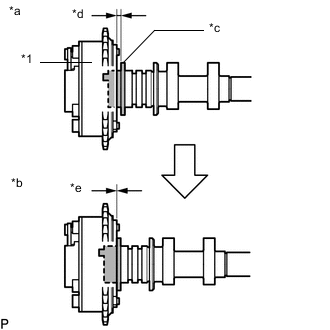
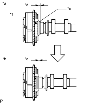
Text in Illustration *1 Camshaft Timing Exhaust Gear Assembly *a Incorrect *b Correct *c No. 2 Camshaft Flange *d Gap *e No Gap Check that there is no gap between the camshaft timing exhaust gear assembly and No. 2 camshaft flange.
-
Secure the camshaft timing exhaust gear assembly with the bolt.
- Torque:
- 85 N*m { 867 kgf*cm, 63 ft.*lbf }
Note
Do not disassemble the camshaft timing exhaust gear assembly.
Tech Tips
Perform "Inspection After Repair" after replacing the camshaft timing exhaust gear assembly Click here.
-
-
SET NO. 1 CYLINDER TO TDC/COMPRESSION
-
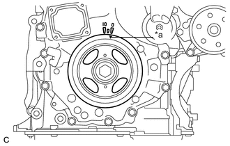
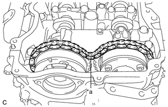
Text in Illustration *a Timing Notch (Groove) Turn the crankshaft pulley until its timing notch (groove) and the timing mark "0" of the timing chain cover assembly are aligned.
-
-
INSTALL NO. 2 CAMSHAFT
-
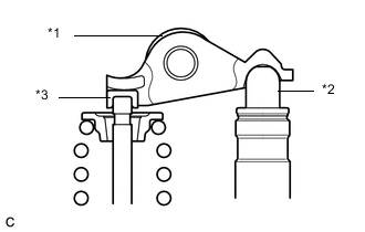
Text in Illustration *1 No. 1 Valve Rocker Arm Sub-assembly *2 Valve Lash Adjuster Assembly *3 Valve Stem Cap Make sure that the No. 1 valve rocker arm sub-assemblies are installed as shown in the illustration.
-
Clean the camshaft journals.
-
Apply a light coat of engine oil to the camshaft journals, camshaft housing sub-assembly and camshaft bearing caps.
-
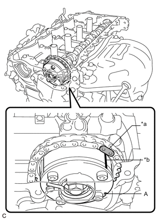
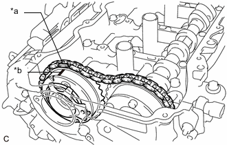
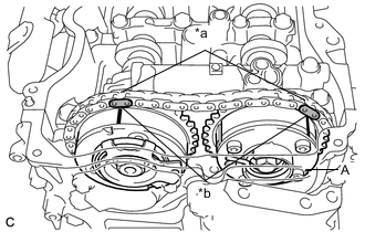
Text in Illustration *a Paint Mark *b Timing Mark Hold up the chain sub-assembly, align the timing mark and paint mark, and install the No. 2 camshaft to the camshaft housing sub-assembly.
Tech Tips
-
"A" is not a timing mark.
-
Perform "Inspection After Repair" after replacing the No. 2 camshaft Click here.
-
-
-
INSTALL CAMSHAFT TIMING GEAR ASSEMBLY
-
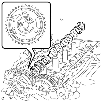
Text in Illustration *a Paint Mark *b Timing Mark Align the paint mark of the chain sub-assembly and the timing mark of the camshaft timing gear assembly. Then install the camshaft timing gear assembly.
Tech Tips
Perform "Inspection After Repair" after replacing the camshaft timing gear assembly Click here.
-
-
INSTALL CAMSHAFT
-
Text in Illustration *1 No. 1 Valve Rocker Arm Sub-assembly *2 Valve Lash Adjuster Assembly *3 Valve Stem Cap Make sure that the No. 1 valve rocker arm sub-assemblies are installed as shown in the illustration.
-
Clean the camshaft journals.
-
Apply a light coat of engine oil to the camshaft journals and camshaft housing sub-assembly.
-
Text in Illustration *a Knock Pin Hole *b Knock Pin Align and fit the knock pin of the camshaft with the knock pin hole of the camshaft timing gear assembly.
Note
Be careful not to damage the contact surface of the camshaft timing gear assembly with the knock pin of the camshaft.
-
Text in Illustration *1 Camshaft Timing Gear Assembly *a Incorrect *b Correct *c Portion (A) of Camshaft *d Gap *e No Gap Check that there is no gap between the camshaft timing gear assembly and portion (A) of the camshaft shown in the illustration.
Tech Tips
Perform "Inspection After Repair" after replacing the camshaft Click here.
-
-
TEMPORARILY INSTALL CAMSHAFT TIMING GEAR BOLT
Note
There are different types of camshaft timing gear bolts. Make sure to check the identification mark to determine the tightening torque.
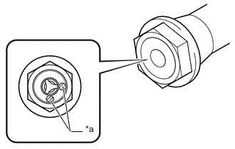
*a Identification Mark Stamp Identification Mark Item Identification Mark Stamp Type A A Type B D
-
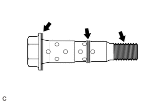
Apply engine oil to the areas of the camshaft timing gear bolt shown in the illustration.
-
Temporarily install the camshaft timing gear bolt.
Tech Tips
Make sure that the camshaft timing gear bolt is screwed in by at least 3 threads.
-
-
INSTALL CAMSHAFT BEARING CAP
-
Place the No. 1 camshaft bearing cap, No. 2 camshaft bearing cap, No. 3 camshaft bearing cap and No. 4 camshaft bearing cap in their correct positions.
-
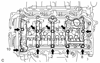
Uniformly tighten the 10 bolts in several steps in the order shown in the illustration.
- Torque:
- 27 N*m { 275 kgf*cm, 20 ft.*lbf }
-
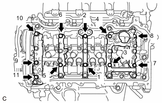
Uniformly tighten the 11 bolts in several steps in the order shown in the illustration.
- Torque:
- 16 N*m { 163 kgf*cm, 12 ft.*lbf }
-
Check the torque of each bolt again.
-
-
TIGHTEN CAMSHAFT TIMING GEAR BOLT
-
Text in Illustration *a Slack Check that there is some slack in the chain sub-assembly as shown in the illustration.
-
Text in Illustration *a Hold 
Turn Use a wrench to hold the hexagonal portion of the camshaft.
-
Tighten the camshaft timing gear bolt.
- Torque:
- Type A
- 120 N*m { 1224 kgf*cm, 89 ft.*lbf }
- Type B
- 95 N*m { 969 kgf*cm, 70 ft.*lbf }
Note
Be careful not to damage the cylinder head sub-assembly or spark plug tube with the wrench.
-
Text in Illustration *a Paint Mark *b Timing Mark Check that the paint marks of the chain sub-assembly are aligned with the timing mark of the camshaft timing gear assembly and camshaft timing exhaust gear assembly.
Tech Tips
"A" is not a timing mark.
-
-
ADD ENGINE OIL
-
INSTALL TIMING CHAIN GUIDE
-
INSTALL NO. 1 CHAIN TENSIONER ASSEMBLY
-
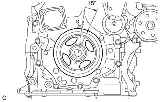
Turn the crankshaft pulley approximately 15° clockwise.
-
Install a new gasket and the No. 1 chain tensioner assembly with the 2 bolts.
- Torque:
- 10 N*m { 102 kgf*cm, 7 ft.*lbf }
Note
Make sure not to drop the gasket inside the timing chain cover assembly.
-
Remove the pin from the stopper plate.
-
-
SET NO. 1 CYLINDER TO TDC/COMPRESSION
-
Turn the crankshaft pulley until its timing notch (groove) and the timing mark "0" of the timing chain cover assembly are aligned.
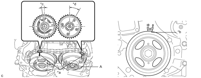
Text in Illustration *a Timing Mark *b Timing Notch (Groove) *c Approximately 7° *d Approximately 32° -
Check that both timing marks on the camshaft timing gear assembly and camshaft timing exhaust gear assembly are facing upward as shown in the illustration. If not, turn the crankshaft 1 revolution (360°) to align the timing marks as shown in the illustration.
Tech Tips
"A" is not a timing mark.
-
-
INSTALL TIMING CHAIN COVER PLATE
-
Install a new gasket and the timing chain cover plate with the 4 bolts.
- Torque:
- 10 N*m { 102 kgf*cm, 7 ft.*lbf }
-
-
INSTALL CAMSHAFT TIMING OIL CONTROL SOLENOID ASSEMBLY
-
INSTALL CYLINDER HEAD COVER SUB-ASSEMBLY
-
CONNECT NO. 2 VENTILATION HOSE
-
INSTALL IGNITION COIL ASSEMBLY
-
INSTALL ENGINE MOVING CONTROL ROD BRACKET
-
INSTALL NO. 2 ENGINE MOUNTING STAY RH
-
INSTALL EARTH WIRE
-
INSTALL VACUUM PUMP ASSEMBLY
-
INSTALL FUEL PUMP WITH SEAL SUB-ASSEMBLY (for High Pressure)
-
CONNECT ENGINE WIRE
-
Connect the engine wire to the engine assembly with the 4 nuts and 5 bolts.
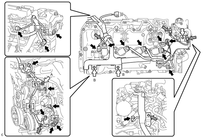
Text in Illustration Connector 
Nut 
Bolt - - - Torque:
- Nut (A)
- 9.8 N*m { 100 kgf*cm, 87 in.*lbf }
- Nut (B) and Bolt
- 8.0 N*m { 82 kgf*cm, 71 in.*lbf }
-
Connect the 18 connectors and 8 clamps.
-
Engage the clamp to connect the heater inlet water hose.
-
-
INSTALL AIR CLEANER CASE SUB-ASSEMBLY
-
INSTALL AIR CLEANER FILTER ELEMENT SUB-ASSEMBLY
-
INSTALL AIR CLEANER CAP WITH AIR CLEANER HOSE
-
INSTALL INLET AIR CLEANER ASSEMBLY
-
INSTALL NO. 1 ENGINE COVER SUB-ASSEMBLY
-
INSTALL COOL AIR INTAKE DUCT SEAL
-
CONNECT CABLE TO NEGATIVE BATTERY TERMINAL
-
INSPECT FOR ENGINE OIL LEAK
-
INSTALL FRONT FENDER APRON SEAL RH
-
INSTALL ENGINE UNDER COVER RH
-
INSTALL FRONT WHEEL OPENING EXTENSION PAD RH
-
INSTALL FRONT WHEEL RH
- Torque:
- 103 N*m { 1049 kgf*cm, 76 ft.*lbf }
-
OPERATION CHECK