ENGINE UNIT REASSEMBLY

PROCEDURE
-
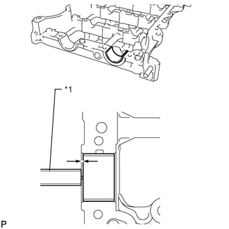
INSTALL STIFFENING CRANKCASE RING PIN
Note
It is not necessary to remove the stiffening crankcase ring pin unless it is being replaced.
-
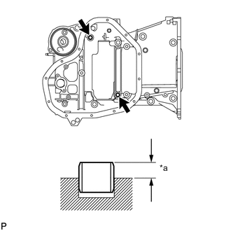
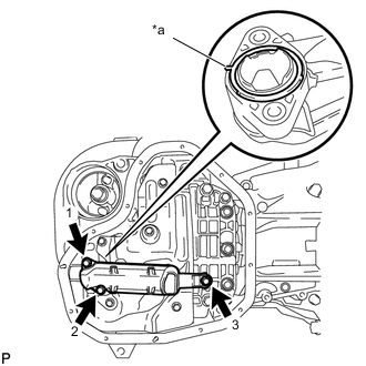
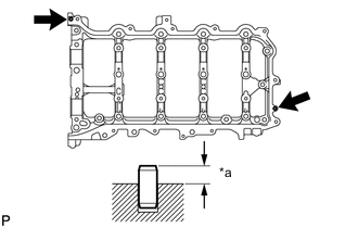
Text in Illustration *a Protrusion Height Using a plastic-faced hammer, tap in 2 new stiffening crankcase ring pins until they stop.
Standard protrusion height 4.3 to 5.3 mm (0.169 to 0.209 in.)
-
-
INSTALL ENGINE BALANCER ASSEMBLY
-
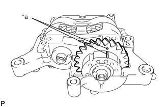
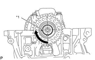
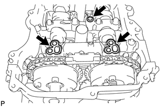
Text in Illustration *a Alignment Mark Check that the alignment marks of the balance shaft damper cover and balance shaft driven gear are aligned.
If the alignment marks are not aligned, align them.
-
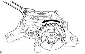
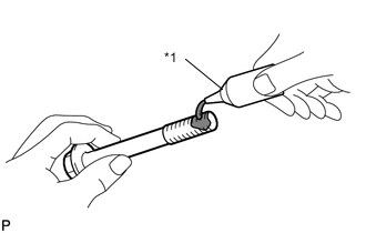
Text in Illustration *1 Driven Gear *2 Damper Cover *a Alignment Mark Place a wrench on the rear cutout part of the No. 2 balance shaft and secure the shaft in place.
-
Rotate the balance shaft driven gear of the No. 1 balance shaft counterclockwise to align the alignment mark of the balance shaft driven gear with the alignment mark of the balance shaft damper cover.
-
-
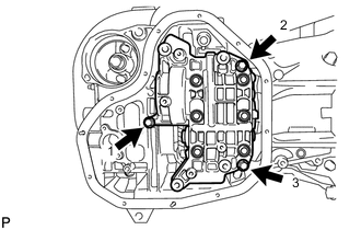
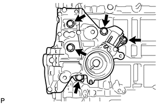
Install the engine balancer assembly to the stiffening crankcase assembly with the 3 bolts, and tighten the bolts in the sequence shown in the illustration.
- Torque:
- 24 N*m { 245 kgf*cm, 18 ft.*lbf }
-
-
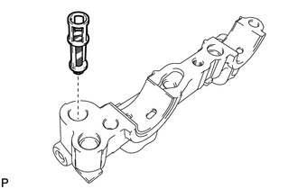
INSTALL STIFFENING CRANKCASE STUD BOLT
Note
If a stiffening crankcase stud bolt is deformed or the threads are damaged, replace it.
-
Using an E5 and E8 "TORX" socket wrench, install the stiffening crankcase stud bolts.
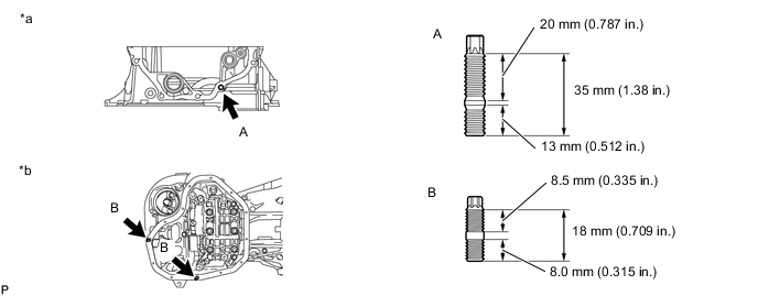
- Torque:
- for Stud Bolt A
- 9.5 N*m { 97 kgf*cm, 84 in.*lbf }
- for Stud Bolt B
- 4.0 N*m { 41 kgf*cm, 35 in.*lbf }
Text in Illustration *a Front Side *b Lower Side
-
-
INSTALL STIFFENING CRANKCASE ASSEMBLY
-
Text in Illustration *1 Crankshaft Pulley Key Rotate the crankshaft clockwise so that the crankshaft pulley key is at the position 90° from the bottom as shown in the illustration.
-
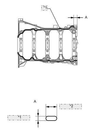
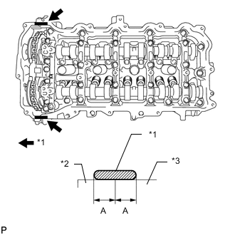
*1 2.5 to 3.5 mm *2 7.0 to 9.0 mm Apply seal packing in a continuous line as shown in the illustration.
Text in Illustration 
Stiffening Crankcase Assembly 
cylinder block sub-assembly Seal packing Toyota Genuine Seal Packing Black, Three Bond 1207B or equivalent Standard Seal Dimension Area Specified Condition Continuous Line 2.5 to 3.5 mm (0.0984 to 0.138 in.) Dashed Line 7.0 to 9.0 mm (0.276 to 0.354 in.) wide and 2.5 to 3.5 mm (0.0984 to 0.138 in.) thick Application Length A 28 mm (1.10 in.) Note
-
Remove any oil from the contact surfaces.
-
Install the oil pan sub-assembly within 3 minutes and tighten the bolts and nuts within 15 minutes after applying seal packing.
-
Do not apply oil for at least 2 hours after the installation.
-
-
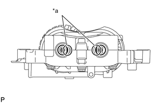
Text in Illustration *a Cutout Check that the rear cutout parts are as shown in the illustration.
-
Clean the bolts and their installation holes.
-
Text in Illustration *1 Adhesive Apply adhesive to 3 or more threads of the ends of the bolts A.
Adhesive Toyota Genuine Adhesive 1344, Three Bond 1344 or equivalent -
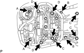
Temporarily install the stiffening crankcase assembly with the 11 bolts.
Bolt Length Item Length Bolt A 65 mm (2.56 in.) Bolt B 35 mm (1.38 in.) Bolt C 125 mm (4.92 in.) Bolt D 165 mm (6.50 in.) Tech Tips
Apply adhesive to the bolts A before installation.
-
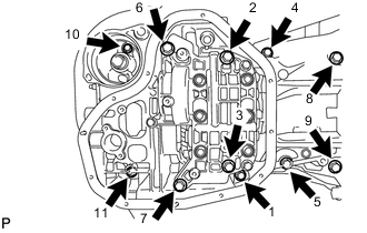
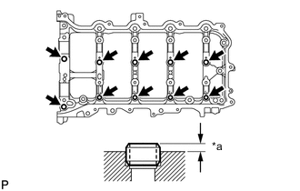
Tighten the 11 bolts in the sequence shown in the illustration to install the stiffening crankcase assembly.
- Torque:
- for Bolt A
- 24 N*m { 245 kgf*cm, 18 ft.*lbf }
- except Bolt A
- 43 N*m { 438 kgf*cm, 32 ft.*lbf }
-
-
INSTALL NO. 1 OIL PAN BAFFLE PLATE
-
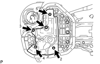
Install the No. 1 oil pan baffle plate and uniformly tighten the 5 bolts in several steps, in the sequence shown in the illustration.
- Torque:
- 10 N*m { 102 kgf*cm, 7 ft.*lbf }
-
-
INSTALL OIL STRAINER SUB-ASSEMBLY
-
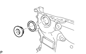
Apply a light coat of engine oil to a new gasket.
-
Text in Illustration *a Protrusion Align the protrusion of the gasket with the cutout of the oil strainer sub-assembly, and install the gasket to the oil strainer sub-assembly.
-
Install the oil strainer sub-assembly with the 3 bolts in several steps, in the sequence shown in the illustration.
- Torque:
- 9.0 N*m { 92 kgf*cm, 80 in.*lbf }
-
-
INSTALL OIL PAN SUB-ASSEMBLY
-
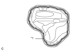
*1 2.5 to 3.5 mm Apply seal packing in a continuous line as shown in the illustration.
Seal packing Toyota Genuine Seal Packing Black, Three Bond 1207B or equivalent Standard seal diameter 2.5 to 3.5 mm (0.0984 to 0.138 in.) Note
-
Remove any oil from the contact surface.
-
Install the oil pan sub-assembly within 3 minutes and tighten the bolts and nuts within 10 minutes after applying seal packing.
-
Do not apply oil for at least 2 hours after the installation.
-
-
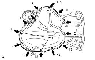
Text in Illustration *1 Nut Install the oil pan sub-assembly with the 11 bolts and 2 nuts in several steps, in the sequence shown in the illustration.
- Torque:
- 10 N*m { 102 kgf*cm, 7 ft.*lbf }
Tech Tips
The bolt A and the nut A are tightened twice.
-
-
INSTALL OIL PAN DRAIN PLUG
-
Install a new gasket and the oil pan drain plug to the oil pan sub-assembly.
- Torque:
- 40 N*m { 408 kgf*cm, 30 ft.*lbf }
-
-
INSTALL OIL FILTER BRACKET CLIP
-
Install the oil filter bracket clip to the stiffening crankcase assembly.
-
-
INSTALL OIL FILTER CAP ASSEMBLY
-
INSTALL REAR ENGINE OIL SEAL
-
INSTALL CYLINDER BLOCK WATER JACKET SPACER
-
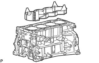
Install the cylinder block water jacket spacer to the cylinder block sub-assembly.
-
-
INSTALL CYLINDER HEAD GASKET
-
INSTALL CYLINDER HEAD SUB-ASSEMBLY
-
SET CAMSHAFT TIMING GEAR ASSEMBLY
-
INSTALL CAMSHAFT BEARING CAP SETTING RING PIN
Note
It is not necessary to remove the camshaft bearing cap setting ring pin unless it is being replaced.
-
Text in Illustration *a Protrusion Height Using a plastic-faced hammer, tap in 10 new camshaft bearing cap setting ring pins to the camshaft housing sub-assembly.
Standard protrusion height 2.7 to 3.3 mm (0.106 to 0.130 in.)
-
-
INSTALL CAMSHAFT HOUSING STRAIGHT PIN
Note
It is not necessary to remove the camshaft housing straight pin unless it is being replaced.
-
Text in Illustration *a Protrusion Height Using a plastic-faced hammer, tap in 2 new camshaft housing straight pins to the camshaft housing sub-assembly.
Standard protrusion height 5.0 to 7.0 mm (0.197 to 0.276 in.)
-
-
INSTALL CAMSHAFT HOUSING STUD BOLT
Note
If a camshaft housing stud bolt is deformed or the threads are damaged, replace it.
-
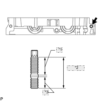
*1 20 mm (0.787 in.) *2 35 mm (1.38 in.) *3 13 mm (0.512 in.) Using an E8 "TORX" socket wrench, install the camshaft housing stud bolt.
- Torque:
- 6.5 N*m { 66 kgf*cm, 58 in.*lbf }
-
-
INSTALL NO. 1 CAMSHAFT BEARING
-
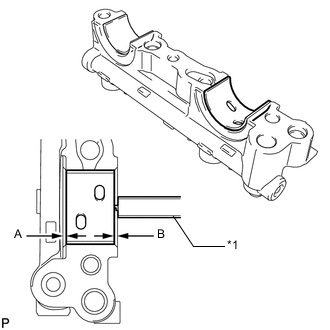
Text in Illustration *1 Vernier Caliper Clean the No. 1 camshaft bearing.
-
Install the No. 1 camshaft bearing to the No. 1 camshaft bearing cap.
-
Using a vernier caliper, measure the distance between the No. 1 camshaft bearing cap edge and the No. 1 camshaft bearing edge.
Standard dimension A - B or B - A 0 to 0.7 mm (0 to 0.0276 in.)
-
-
INSTALL NO. 2 CAMSHAFT BEARING
-
Clean the No. 2 camshaft bearing.
-
Install the No. 2 camshaft bearing to the camshaft housing sub-assembly.
-
Text in Illustration *1 Vernier Caliper Using a vernier caliper, measure the distance between the camshaft housing sub-assembly edge and the No. 2 camshaft bearing edge.
Standard distance 1.15 to 1.85 mm (0.0453 to 0.0728 in.)
-
-
INSTALL OIL CONTROL VALVE FILTER
-
Install the oil control valve filter to the No. 1 camshaft bearing cap.
-
-
INSTALL CAMSHAFT
-
INSTALL CAMSHAFT BEARING CAP
-
INSTALL VALVE STEM CAP
-
INSTALL VALVE LASH ADJUSTER ASSEMBLY
-
INSTALL NO. 1 VALVE ROCKER ARM SUB-ASSEMBLY
-
INSTALL CAMSHAFT HOUSING SUB-ASSEMBLY
-
INSTALL CAMSHAFT TIMING GEAR ASSEMBLY
-
INSTALL CAMSHAFT TIMING EXHAUST GEAR ASSEMBLY
-
INSTALL CRANKSHAFT TIMING SPROCKET
-
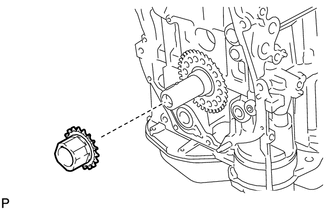
Install the crankshaft timing sprocket to the crankshaft.
-
-
ADD ENGINE OIL
-
SET NO. 1 CYLINDER TO TDC/COMPRESSION
-
INSTALL NO. 1 CHAIN VIBRATION DAMPER
-
INSTALL CHAIN SUB-ASSEMBLY
-
INSTALL CHAIN TENSIONER SLIPPER
-
INSTALL NO. 1 CHAIN TENSIONER ASSEMBLY
-
INSTALL TIMING CHAIN GUIDE
-
SET NO. 1 CYLINDER TO TDC/COMPRESSION
-
INSTALL TIMING CHAIN COVER PLATE
-
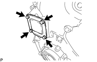
Install a new gasket and the timing chain cover plate with the 4 bolts.
- Torque:
- 10 N*m { 102 kgf*cm, 7 ft.*lbf }
-
-
INSTALL TIMING CHAIN COVER TIGHT PLUG
-
Using a 14 mm hexagon wrench, install a new gasket and the timing chain cover tight plug.
- Torque:
- 30 N*m { 306 kgf*cm, 22 ft.*lbf }
-
-
INSTALL TIMING CHAIN COVER SUB-ASSEMBLY
-
INSTALL ENGINE MOUNTING BRACKET RH
-
INSTALL TIMING CHAIN COVER OIL SEAL
-
INSTALL SPARK PLUG TUBE GASKET
-
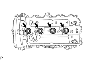
Tap in 4 new spark plug tube gaskets to the cylinder head cover sub-assembly.
Note
After pressing in the spark plug tube gasket, make sure the gasket protrudes 1.0 mm (0.0394 in.) or less from the cylinder head cover sub-assembly.
-
-
INSTALL CYLINDER HEAD COVER SUB-ASSEMBLY
-
Apply a light coat of engine oil to 3 new camshaft bearing cap oil hole gaskets.
-
Install the 3 camshaft bearing cap oil hole gaskets.
-
Install a new cylinder head cover gasket to the cylinder head cover sub-assembly.
Note
Remove any oil from the contact surface.
-
Text in Illustration *1 Seal Packing *2 Timing Chain Cover Sub-assembly *3 Camshaft Housing Sub-assembly Apply seal packing as shown in the illustration.
Seal packing Toyota Genuine Seal Packing Black, Three Bond 1207B or equivalent Standard seal diameter 3.0 to 6.0 mm (0.118 to 0.236 in.) Application width A 5.0 mm (0.197 in.) Note
-
Remove any oil from the contact surface.
-
Install the cylinder head cover sub-assembly within 3 minutes and tighten the bolts within 15 minutes after applying seal packing.
-
-
Align the cylinder head cover sub-assembly with the pin A. Then align the cylinder head cover sub-assembly with the pin B and install the cylinder head cover sub-assembly.
-
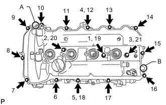
Install 3 new seal washers and the 16 bolts, and then tighten the bolts in the order shown in the illustration.
- Torque:
- 12 N*m { 122 kgf*cm, 9 ft.*lbf }
Note
Do not apply oil for at least 2 hours after the installation.
-
-
INSTALL CRANKSHAFT PULLEY
-
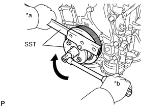
Text in Illustration *a Hold *b Turn Align the crankshaft pulley key with the key groove of the crankshaft pulley.
-
Using SST, hold the crankshaft pulley and install the pulley bolt.
- SST
- 09213-54015
- 09330-00021
- Torque:
- 260 N*m { 2651 kgf*cm, 192 ft.*lbf }
Tech Tips
SST (Crankshaft pulley holding tool) Fixing bolt part No. : 91551-80650(2 pcs)
-
-
INSTALL CRANKSHAFT POSITION SENSOR
-
INSTALL WATER INLET HOUSING
-
Install a new gasket and the water inlet housing with the 4 bolts and nut.
- Torque:
- 43 N*m { 438 kgf*cm, 32 ft.*lbf }
-
-
INSTALL ENGINE WATER PUMP ASSEMBLY
-
INSTALL V-RIBBED BELT TENSIONER ASSEMBLY
-
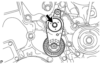
Install the V-ribbed belt tensioner assembly with the bolt.
- Torque:
- 21 N*m { 214 kgf*cm, 15 ft.*lbf }
-
-
INSTALL THERMOSTAT
-
INSTALL WATER INLET
-
INSTALL NO. 1 WATER BY-PASS PIPE
-
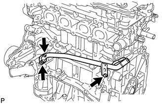
Install a new gasket and the No. 1 water by-pass pipe with the 2 nuts and bolt.
- Torque:
- 12 N*m { 122 kgf*cm, 9 ft.*lbf }
-
-
INSTALL SEPARATOR CASE
-
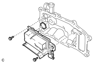
Apply a light coat of engine oil to a new gasket.
-
Install the gasket to the separator case.
-
Install the separator case to the ventilation case sub-assembly with the 2 bolts.
- Torque:
- 10 N*m { 102 kgf*cm, 7 ft.*lbf }
-
-
INSTALL VENTILATION CASE SUB-ASSEMBLY
-
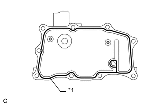
*1 2.5 to 3.5 mm Apply seal packing in a continuous line as shown in the illustration.
Seal packing Toyota Genuine Seal Packing Black, Three Bond 1207B or equivalent Standard seal diameter 2.5 to 3.5 mm (0.0984 to 0.138 in.) Note
-
Remove any oil from the contact surface.
-
Install the ventilation case sub-assembly within 3 minutes and tighten the bolts and nuts within 15 minutes after applying seal packing.
-
-
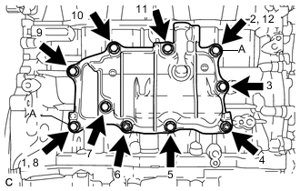
Install the ventilation case sub-assembly, and install the 8 bolts and 2 nuts in the order shown in the illustration.
- Torque:
- 21 N*m { 214 kgf*cm, 15 ft.*lbf }
Tech Tips
The bolt A is tightened twice.
-
-
INSTALL VENTILATION VALVE SUB-ASSEMBLY
-
INSTALL CAMSHAFT POSITION SENSOR
-
INSTALL CAMSHAFT TIMING OIL CONTROL VALVE ASSEMBLY
-
INSTALL OIL FILLER CAP SUB-ASSEMBLY
-
Install a new gasket to the oil filler cap sub-assembly.
-
Install the oil filler cap sub-assembly to the cylinder head cover sub-assembly.
-
-
INSTALL SPARK PLUG
-
INSTALL ENGINE COVER JOINT
-
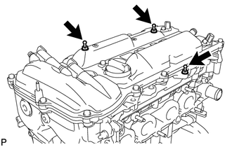
Install the 3 engine cover joints.
- Torque:
- 10 N*m { 102 kgf*cm, 7 ft.*lbf }
-