FRONT BUMPER REASSEMBLY
PROCEDURE
-
INSTALL FRONT BUMPER REINFORCEMENT SUB-ASSEMBLY
-
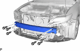
Install the front bumper reinforcement sub-assembly with the 6 bolts.
- Torque:
- 61 N*m { 622 kgf*cm, 45 ft.*lbf }
-
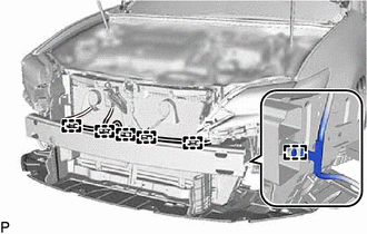
Engage the 6 clamps.
-
-
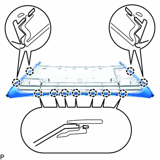
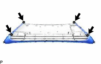
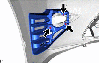
INSTALL FRONT BUMPER ENERGY ABSORBER
-
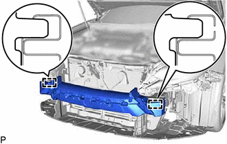
Engage the 2 guides to install the front bumper energy absorber.
-
-
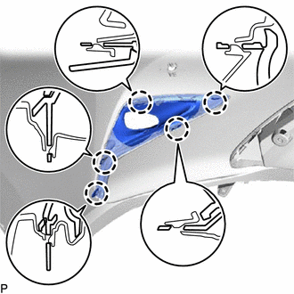
INSTALL FRONT BUMPER STAY LH
-
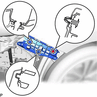
Engage the 3 claws.
-
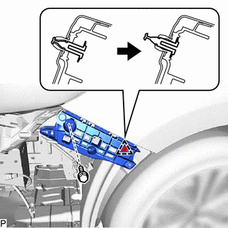
Engage the clip as shown in the illustration.
-
Install the front bumper stay LH with the bolt.
- Torque:
- 5.4 N*m { 55 kgf*cm, 48 in.*lbf }
-
-
INSTALL FRONT BUMPER STAY RH
Tech Tips
Use the same procedure as for the LH side.
-
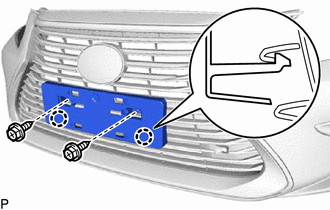
INSTALL LOWER RADIATOR GRILLE MOULDING
-
Engage the 11 claws.
-
Install the lower radiator grille moulding with the 4 screws.
-
-
INSTALL FRONT BUMPER HOLE COVER LH
-
Engage the 4 claws.
-
Install the front bumper hole cover LH with the screw.
-
-
INSTALL FRONT BUMPER HOLE COVER RH
Tech Tips
Use the same procedure as for the LH side.
-
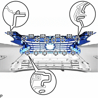
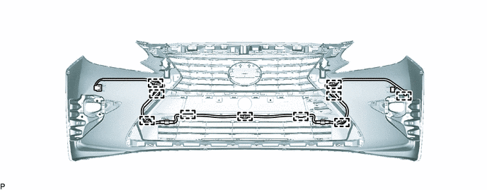
INSTALL LOWER RADIATOR GRILLE SUB-ASSEMBLY
-
Engage the 16 claws to install the lower radiator grille sub-assembly.
-
-
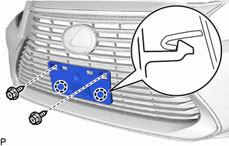
INSTALL RADIATOR GRILLE MOULDING
-
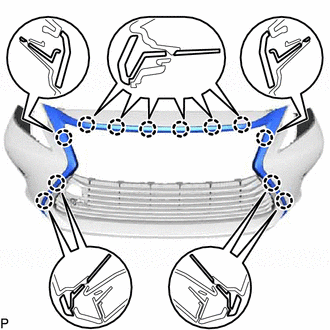
Engage the 12 claws.
-
Install the radiator grille moulding with the 4 screws.
-
-
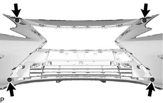
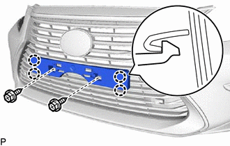
INSTALL RADIATOR GRILLE
-
Engage the 6 guides and 12 claws to install the radiator grille.
-
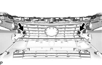
Install the 2 screws.
-
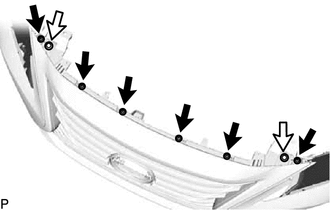
Install the radiator grille with the 6 screws and 2 clips.
Text in Illustration 
Screw 
Clip
-
-
INSTALL RADIATOR GRILLE (OR FRONT PANEL) EMBLEM
-
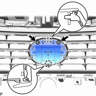
Engage the claw and guide.
-
Install the radiator grille (or front panel) emblem with 2 new spring nuts.
-
-
INSTALL MILLIMETER WAVE RADAR SENSOR ASSEMBLY (w/ Pre-crash Safety System)
-
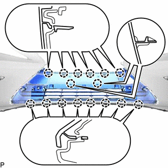
INSTALL RADIATOR GRILLE SEAL
-
Clean the front bumper assembly.
-
Remove any remaining double-sided tape from the front bumper assembly.
-
Wipe off any tape adhesive residue with cleaner.
-
-
Remove the release paper from a new radiator grille seal.
Tech Tips
After removing the release paper, keep the exposed adhesive free from foreign matter.
-
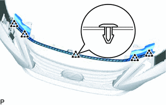
Engage the 5 clips to install the radiator grille seal.
Text in Illustration 
Double-sided Tape
-
-
INSTALL FOG LIGHT COVER LH
-
Engage the 5 claws to install the fog light cover LH.
-
-
INSTALL FOG LIGHT COVER RH
Tech Tips
Use the same procedure as for the LH side.
-
INSTALL FOG LIGHT MOUNTING BRACKET LH
-
Install the fog light mounting bracket LH with the 3 screws.
-
-
INSTALL FOG LIGHT MOUNTING BRACKET RH
Tech Tips
Use the same procedure as for the LH side.
-
INSTALL FRONT BUMPER HOLE COVER
-
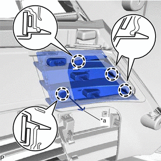
Text in Illustration *a Hook Engage the hook.
-
Engage the 4 claws to install the front bumper hole cover.
-
-
INSTALL FRONT FENDER LINER RETAINER
-
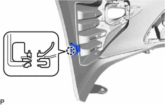
Engage the claw to install the front fender liner retainer.
Tech Tips
Use the same procedure for the RH side and LH side.
-
-
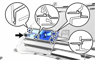
INSTALL FRONT BUMPER EXTENSION MOUNTING BRACKET (for Type A)
-
Engage the 4 claws.
-
Install the front bumper extension mounting bracket with the 2 screws.
-
-
INSTALL FRONT BUMPER EXTENSION MOUNTING BRACKET (for Type B)
-
Engage the 2 claws.
-
Install the front bumper extension mounting bracket with the 2 screws.
-
-
INSTALL FRONT BUMPER EXTENSION MOUNTING BRACKET (Type C)
-
Engage the 2 claws.
-
Install the front bumper extension mounting bracket with the 2 screws.
-
-
INSTALL NO. 4 ENGINE ROOM WIRE (w/ LEXUS Parking Assist-sensor System)
-
Engage the 10 clamps to install the No. 4 engine room wire.
-
-
INSTALL NO. 2 ULTRASONIC SENSOR RETAINER (w/ LEXUS Parking Assist-sensor System)
-
INSTALL NO. 2 ULTRASONIC SENSOR WITH CLIP (w/ LEXUS Parking Assist-sensor System)
-
INSTALL NO. 1 ULTRASONIC SENSOR WITH CLIP (w/ LEXUS Parking Assist-sensor System)
-
INSTALL FOG LIGHT ASSEMBLY LH
-
INSTALL FOG LIGHT ASSEMBLY RH
Tech Tips
Use the same procedure as for the LH side.