LIGHTING SYSTEM Front Fog Light Circuit
DESCRIPTION
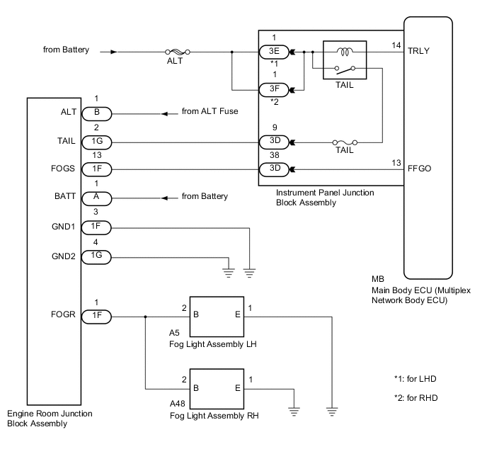
- except 6AR-FSE:
The main body ECU (multiplex network body ECU) controls the front fog lights via the engine room junction block assembly.
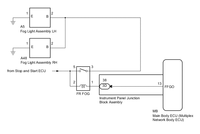
- for 6AR-FSE:
The main body ECU (multiplex network body ECU) controls the front fog lights via the FR FOG relay.
WIRING DIAGRAM
-
except 6AR-FSE:
-
for 6AR-FSE:
CAUTION / NOTICE / HINT
Note
-
Inspect the fuses for circuits related to this system before performing the following inspection procedure.
-
If the main body ECU (multiplex network body ECU) is replaced, refer to Service Bulletin.
PROCEDURE
-
CONFIRM MODEL
Result Result Proceed to except 6AR-FSE A for 6AR-FSE B
B 
PERFORM ACTIVE TEST USING GTS Click here
A 
-
CHECK OPERATION (TAILLIGHTS)
-
Check the operation of the taillights.
OK Taillights operate normally.
NG 
GO TO PROBLEM SYMPTOMS TABLE Click here
OK
-
-
PERFORM ACTIVE TEST USING GTS
-
Connect the GTS to the DLC3.
-
Turn the engine switch on (IG).
-
Turn the GTS on.
-
Enter the following menus: Body Electrical / Main Body / Active Test.
-
Perform the Active Test according to the display on the GTS.
Main Body Tester Display Test Part Control Range Diagnostic Note Front Fog Light Relay Front fog light relay ON/OFF Light control switch is in tail position OK Front fog light relay operates. (Front fog lights come on.)
OK
PROCEED TO NEXT SUSPECTED AREA SHOWN IN PROBLEM SYMPTOMS TABLE Click here
NG
-
-
CHECK ENGINE ROOM JUNCTION BLOCK ASSEMBLY
-
Using a voltmeter, check the signal reading of the engine room junction block assembly Click here.
OK Output signal reading is normal.
NG
INSPECT ENGINE ROOM JUNCTION BLOCK ASSEMBLY (RESULTS OF SIGNAL READING CHECK) Click here
OK
-
-
CHECK HARNESS AND CONNECTOR (ENGINE ROOM JUNCTION BLOCK ASSEMBLY POWER SOURCE AND BODY GROUND)
-
Remove the engine room junction block assembly from the engine room relay block and junction block assembly Click here.
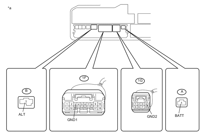
Text in Illustration *a Component without engine room junction block assembly connected
(Engine Room Relay Block and Junction Block Assembly)
- - -
Measure the voltage according to the value(s) in the table below.
Standard Voltage Tester Connection Condition Specified Condition A-1 (BATT) - Body ground Always 11 to 14 V B-1 (ALT) - Body ground Always 11 to 14 V -
Measure the resistance according to the value(s) in the table below.
Standard Resistance Tester Connection Condition Specified Condition 1F-3 (GND1) - Body ground Always Below 1 Ω 1G-4 (GND2) - Body ground Always Below 1 Ω
NG
REPAIR OR REPLACE HARNESS OR CONNECTOR
OK
-
-
CHECK HARNESS AND CONNECTOR (INSTRUMENT PANEL JUNCTION BLOCK ASSEMBLY - ENGINE ROOM JUNCTION BLOCK ASSEMBLY)
-
Disconnect the 3D instrument panel junction block assembly connector.
-
Measure the resistance according to the value(s) in the table below.
Standard Resistance Tester Connection Condition Specified Condition 1G-2 (TAIL) - 3D-9 Always Below 1 Ω 3D-9 - Body ground Always 10 kΩ or higher 1F-13 (FOGS) - 3D-38 Always Below 1 Ω 3D-38 - Body ground Always 10 kΩ or higher
NG
REPAIR OR REPLACE HARNESS OR CONNECTOR
OK
-
-
INSPECT INSTRUMENT PANEL JUNCTION BLOCK ASSEMBLY
-
Remove the instrument panel junction block assembly Click here.
-
Remove the main body ECU (multiplex network body ECU) from the instrument panel junction block assembly.
-
Measure the resistance according to the value(s) in the table below.
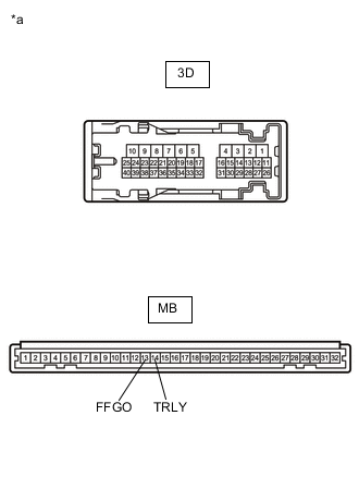
Standard Resistance Tester Connection Condition Specified Condition MB-13 (FFGO) - 3D-38 Always Below 1 Ω 3D-38 - Body ground Always 10 kΩ or higher -
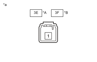
Connect a positive (+) lead from the battery to terminal 3E-1*1 or 3F-1*2.
-
Connect a negative (-) lead from the battery to terminal MB-14 (TRLY).
-
Measure the voltage according to the value(s) in the table below.
Standard Voltage Tester Connection Condition Specified Condition 3D-9 - Body ground Always 11 to 14 V
-
*1: for LHD
-
*2: for RHD
Text in Illustration *A for LHD *B for RHD *a Component without harness connected
(Instrument Panel Junction Block Assembly)
-
NG
REPLACE INSTRUMENT PANEL JUNCTION BLOCK ASSEMBLY Click here
OK
-
-
CHECK ENGINE ROOM JUNCTION BLOCK ASSEMBLY
-
Replace the engine room junction block assembly with a new or known good one Click here.
-
Check that the fog lights operate normally.
OK The fog lights operate normally.
OK
END (ENGINE ROOM JUNCTION BLOCK ASSEMBLY WAS DEFECTIVE)
NG
REPLACE MAIN BODY ECU (MULTIPLEX NETWORK BODY ECU) Click here
-
-
PERFORM ACTIVE TEST USING GTS
-
Connect the GTS to the DLC3.
-
Turn the engine switch on (IG).
-
Turn the GTS on.
-
Enter the following menus: Body Electrical / Main Body / Active Test.
-
Perform the Active Test according to the display on the GTS.
Main Body Tester Display Test Part Control Range Diagnostic Note Front Fog Light Relay Front fog light relay ON/OFF Light control switch is in tail position OK Front fog light relay operates. (Front fog lights come on.)
OK
GO TO PROBLEM SYMPTOMS TABLE Click here
NG
-
-
INSPECT FR FOG RELAY
-
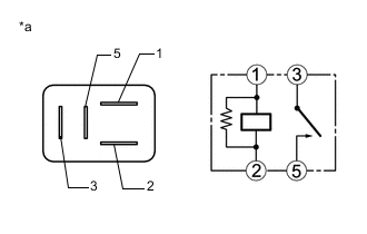
Text in Illustration *a Component without harness connected
(FR FOG Relay)
Remove the FR FOG relay from the engine room relay block and junction block assembly.
-
Measure the resistance according to the value(s) in the table below.
Standard Resistance Tester Connection Condition Specified Condition 3 - 5 Voltage not applied between terminals 1 and 2 10 kΩ or higher 3 - 5 Voltage applied between terminals 1 and 2 Below 1 Ω
NG
REPLACE FR FOG RELAY
OK
-
-
CHECK HARNESS AND CONNECTOR (POWER SOURCE - FR FOG RELAY)
-
Measure the voltage according to the value(s) in the table below.
Standard Voltage Tester Connection Condition Specified Condition Relay terminal 2 - Body ground Always 11 to 14 V Relay terminal 5 - Body ground Always 11 to 14 V
NG
GO TO STOP AND START SYSTEM Click here
OK
-
-
CHECK HARNESS AND CONNECTOR (FR FOG RELAY - INSTRUMENT PANEL JUNCTION BLOCK ASSEMBLY)
-
Disconnect the 3D instrument panel junction block assembly connector.
-
Measure the resistance according to the value(s) in the table below.
Standard Resistance Tester Connection Condition Specified Condition Relay terminal 1 - 3D-38 Always Below 1 Ω Relay terminal 1 - Body ground Always 10 kΩ or higher
NG
REPAIR OR REPLACE HARNESS OR CONNECTOR
OK
-
-
INSPECT INSTRUMENT PANEL JUNCTION BLOCK ASSEMBLY
-
Remove the instrument panel junction block assembly Click here.
-
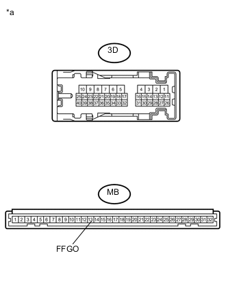
Text in Illustration *a Component without harness connected
(Instrument Panel Junction Block Assembly)
Remove the main body ECU (multiplex network body ECU) from the instrument panel junction block assembly.
-
Measure the resistance according to the value(s) in the table below.
Standard Resistance Tester Connection Condition Specified Condition MB-13 (FFGO) - 3D-38 Always Below 1 Ω
NG
REPLACE INSTRUMENT PANEL JUNCTION BLOCK ASSEMBLY Click here
OK
-
-
CHECK HARNESS AND CONNECTOR (FR FOG RELAY - FOG LIGHT ASSEMBLY LH AND FOG LIGHT ASSEMBLY)
-
Disconnect the A5 fog light assembly LH connector.
-
Disconnect the A48 fog light assembly RH connector.
-
Measure the resistance according to the value(s) in the table below.
Standard Resistance Tester Connection Condition Specified Condition Relay terminal 3 - A5-2 (B) Always Below 1 Ω Relay terminal 3 - A48-2 (B) Always Below 1 Ω Relay terminal 3 - Body ground Always 10 kΩ or higher
OK
REPLACE MAIN BODY ECU (MULTIPLEX NETWORK BODY ECU) Click here
NG
REPAIR OR REPLACE HARNESS OR CONNECTOR
-