RAIN SENSOR ON-VEHICLE INSPECTION
PROCEDURE
-
INSPECT RAIN SENSOR
-
for LHD
-
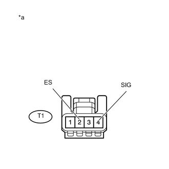
Text in Illustration *a Front view of wire harness connector
(to Rain Sensor)
Disconnect the T1 rain sensor connector.
-
Measure the voltage according to the value(s) in the table below.
Standard Voltage Tester Connection Condition Specified Condition T1-4 (SIG) - T1-2 (ES) Engine switch on (IG) 11 to 14 V -
Measure the resistance according to the value(s) in the table below.
Standard Resistance Tester Connection Condition Specified Condition T1-2 (ES) - Body ground Always Below 1 Ω If the result is not as specified, repair or replace the harness or connector.
-
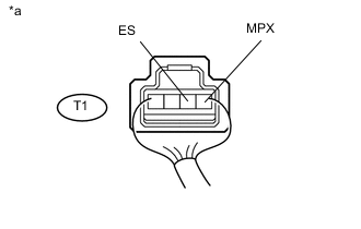
Text in Illustration *a Component with harness connected
(Rain Sensor)
Reconnect the T1 rain sensor connector.
-
Connect an oscilloscope to the rain sensor connector.
-
Check for pulses.
OK Tester Connection Condition Specified Condition T1-1 (MPX) - T1-2 (ES) Engine switch on (IG) Pulse generation If the result is not as specified, replace the rain sensor.
-
-
for RHD, w/o Pre-Crash Safety System
-
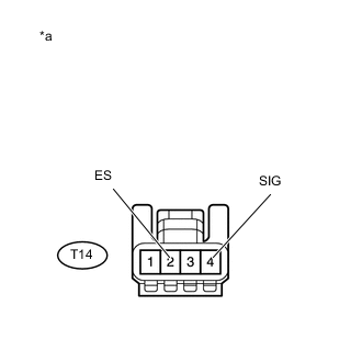
Text in Illustration *a Front view of wire harness connector
(to Rain Sensor)
Disconnect the T14 rain sensor connector.
-
Measure the voltage according to the value(s) in the table below.
Standard Voltage Tester Connection Condition Specified Condition T14-4 (SIG) - T14-2 (ES) Engine switch on (IG) 11 to 14 V -
Measure the resistance according to the value(s) in the table below.
Standard Resistance Tester Connection Condition Specified Condition T14-2 (ES) - Body ground Always Below 1 Ω If the result is not as specified, repair or replace the harness or connector.
-
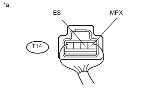
Text in Illustration *a Component with harness connected
(Rain Sensor)
Reconnect the T14 rain sensor connector.
-
Connect an oscilloscope to the rain sensor connector.
-
Check for pulses.
OK Tester Connection Condition Specified Condition T14-1 (MPX) - T14-2 (ES) Engine switch on (IG) Pulse generation If the result is not as specified, replace the rain sensor.
-
-
for RHD, w/ Pre-Crash Safety System
-
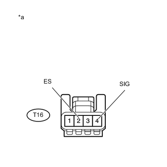
Text in Illustration *a Front view of wire harness connector
(to Rain Sensor)
Disconnect the T16 rain sensor connector.
-
Measure the voltage according to the value(s) in the table below.
Standard Voltage Tester Connection Condition Specified Condition T16-4 (SIG) - T16-2 (ES) Engine switch on (IG) 11 to 14 V -
Measure the resistance according to the value(s) in the table below.
Standard Resistance Tester Connection Condition Specified Condition T16-2 (ES) - Body ground Always Below 1 Ω If the result is not as specified, repair or replace the harness or connector.
-
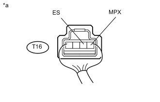
Text in Illustration *a Component with harness connected
(Rain Sensor)
Reconnect the T16 rain sensor connector.
-
Connect an oscilloscope to the rain sensor connector.
-
Check for pulses.
OK Tester Connection Condition Specified Condition T16-1 (MPX) - T16-2 (ES) Engine switch on (IG) Pulse generation If the result is not as specified, replace the rain sensor.
-
-