POWER MIRROR CONTROL SYSTEM(w/ Reverse Shift-linked Mirror) Reverse Shift-linked Function of Power Mirrors does not Operate
SYSTEM DESCRIPTION
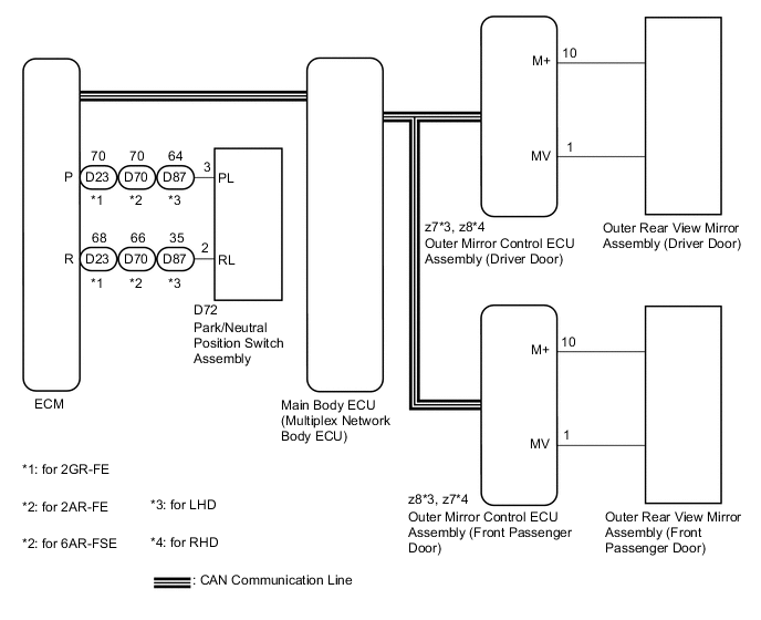
On receiving a reverse signal from the park/neutral position switch assembly, the ECM sends the reverse signal to the main body ECU (multiplex network body ECU) via CAN communication. When receiving the reverse signal, the main body ECU (multiplex network body ECU) sends the reverse request signal to each outer mirror control ECU. Each outer mirror control ECU then performs control in response to the reverse signal.
WIRING DIAGRAM
CAUTION / NOTICE / HINT
Note
-
The reverse shift-linked function will not activate when the mirror select switch is in the neutral position (off).
-
If the main body ECU (multiplex network body ECU) is replaced, refer to Service Bulletin.
PROCEDURE
-
CHECK MEMORY AND REACTIVATION FUNCTION
-
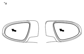
Text in Illustration *a Turn to Fully Left Position Turn the engine switch on (IG).
-
Using the outer mirror switch assembly, turn the mirror surface to the fully left position.
-
Press the M1 switch while the SET switch is being pressed.
-
Check that the buzzer sounds for 0.5 seconds and the mirror surface position is memorized.
-
Using the outer mirror switch assembly, turn the mirror surface to the fully right position.
-
Press the M1 switch.
-
Check that the buzzer sounds for 0.1 seconds and the outer mirror automatically moves to the recorded fully left position.
Result Result Proceed to Memory and reactivation functions are normal. A Memory function is not normal. B Reactivation function is not normal. C
B 
GO TO OTHER DIAGNOSIS PROCEDURE (Power Mirror Surface Position is not Memorized) Click here
C
GO TO OTHER DIAGNOSIS PROCEDURE (Power Mirrors do not Return to Memorized Position) Click here
A 
-
-
CHECK CAN COMMUNICATION SYSTEM
-
Check for CAN communication system DTCs Click here.*1
-
Check for CAN communication system DTCs Click here.*2
-
*1: w/o Central Gateway ECU
-
*2: w/ Central Gateway ECU
Result Result Proceed to CAN DTCs are not output A CAN DTCs are output (w/o central gateway ECU) B CAN DTCs are output (w/ central gateway ECU) C -
B
GO TO CAN COMMUNICATION SYSTEM Click here
C
GO TO CAN COMMUNICATION SYSTEM Click here
A
-
-
CHECK FOR DTC
-
Connect the GTS to the DLC3.
-
Turn the engine switch on (IG).
-
Turn the GTS on.
-
Enter the following menus: Powertrain / Engine / DTC.
-
Check if SFI system DTCs are output.
OK SFI system DTCs are not output. Result Result Proceed to OK A NG (for 2GR-FE) B NG (for 2AR-FE) C NG (for 6AR-FSE) D
B
GO TO SFI SYSTEM (for 2GR-FE) (DIAGNOSTIC TROUBLE CODE CHART) Click here
C
GO TO SFI SYSTEM (for 2AR-FE) (DIAGNOSTIC TROUBLE CODE CHART) Click here
D
GO TO SFI SYSTEM (for 6AR-FSE) (DIAGNOSTIC TROUBLE CODE CHART) Click here
A
-
-
CHECK COMBINATION METER ASSEMBLY
-
Check if the shift position indicator light in the combination meter assembly operates normally.
OK The shift position indicator light indicates the actual shift position correctly.
NG
GO TO METER / GAUGE SYSTEM (PROBLEM SYMPTOMS TABLE) Click here
OK
-
-
CHECK REVERSE SHIFT-LINKED FUNCTION
-
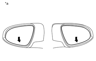
Text in Illustration *a Turns Downward Turn the engine switch on (IG).
-
Set the mirror select switch to L or R.
-
Check that the mirror surface turns downward when the shift lever is moved to R.
Result Result Proceed to Reverse shift-linked functions on both mirrors are not normal A Reverse shift-linked function on driver door is not normal B Reverse shift-linked function on front passenger door is not normal C
A
REPLACE MAIN BODY ECU (MULTIPLEX NETWORK BODY ECU) Click here
B
REPLACE OUTER MIRROR CONTROL ECU ASSEMBLY (DRIVER DOOR) Click here
C
REPLACE OUTER MIRROR CONTROL ECU ASSEMBLY (FRONT PASSENGER DOOR) Click here
-