POWER MIRROR CONTROL SYSTEM(w/ Reverse Shift-linked Mirror) Power Mirror cannot be Adjusted with Power Mirror Switch
SYSTEM DESCRIPTION
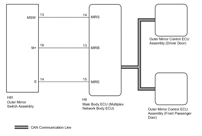
The main body ECU (multiplex network body ECU) detects the mirror adjust switch status and sends the signal to each outer mirror control ECU assembly via CAN communication. Based on this signal, each outer mirror control ECU assembly operates the vertical and horizontal mirror motors to adjust the mirror surface position.
WIRING DIAGRAM
CAUTION / NOTICE / HINT
Note
If the main body ECU (multiplex network body ECU) is replaced, refer to Service Bulletin.
PROCEDURE
-
CHECK CAN COMMUNICATION SYSTEM
-
Check for CAN communication system DTCs Click here.*1
-
Check for CAN communication system DTCs Click here.*2
-
*1: w/o Central Gateway ECU
-
*2: w/ Central Gateway ECU
Result Result Proceed to CAN DTCs are not output A CAN DTCs are output (w/o central gateway ECU) B CAN DTCs are output (w/ central gateway ECU) C -
B 
GO TO CAN COMMUNICATION SYSTEM (DIAGNOSTIC TROUBLE CODE CHART) Click here
C
GO TO CAN COMMUNICATION SYSTEM (DIAGNOSTIC TROUBLE CODE CHART) Click here
A 
-
-
READ VALUE USING GTS (OUTER MIRROR SWITCH ASSEMBLY)
-
Connect the GTS to the DLC3.
-
Turn the engine switch on (IG).
-
Turn the GTS on.
-
Enter the following menus: Body Electrical / Main Body / Data List.
-
Read the Data List according to the display on the GTS.
Main Body Tester Display Measurement Item/Range Normal Condition Diagnostic Note Mirror Selection SW (R) Mirror select switch signal for RH mirror / ON or OFF ON: Mirror select switch in R position
OFF: Mirror select switch off or in L position
- Mirror Selection SW (L) Mirror select switch signal for LH mirror / ON or OFF ON: Mirror select switch in L position
OFF: Mirror select switch off or in R position
- Mirror Position SW (R) Mirror adjust switch signal (Right) / ON or OFF ON: Mirror adjust switch pressed right
OFF: Mirror adjust switch not pressed right
Check with the mirror select switch in any position except neutral Mirror Position SW (L) Mirror adjust switch signal (Left) / ON or OFF ON: Mirror adjust switch pressed left
OFF: Mirror adjust switch not pressed left
Check with the mirror select switch in any position except neutral Mirror Position SW (Up) Mirror adjust switch signal (Up) / ON or OFF ON: Mirror adjust switch pressed up
OFF: Mirror adjust switch not pressed up
Check with the mirror select switch in any position except neutral Mirror Position SW (Dwn) Mirror adjust switch signal (Down) / ON or OFF ON: Mirror adjust switch pressed down
OFF: Mirror adjust switch not pressed down
Check with the mirror select switch in any position except neutral OK On the GTS screen, ON or OFF is displayed for each item according to the table above.
OK
REPLACE MAIN BODY ECU (MULTIPLEX NETWORK BODY ECU) Click here
NG
-
-
INSPECT OUTER MIRROR SWITCH ASSEMBLY
-
Remove the outer mirror switch assembly Click here.
-
Inspect the outer mirror switch assembly Click here.
NG
REPLACE OUTER MIRROR SWITCH ASSEMBLY Click here
OK
-
-
CHECK HARNESS AND CONNECTOR (OUTER MIRROR SWITCH - MAIN BODY ECU)
-
Disconnect the H81 outer mirror switch assembly connector.
-
Disconnect the H9 main body ECU (multiplex network body ECU) connector.
-
Measure the resistance according to the value(s) in the table below.
Standard Resistance Tester Connection Condition Specified Condition H81-14 (E) - H9-15 (MIRE) Always Below 1 Ω H81-16 (M+) - H9-13 (MIRB) Always Below 1 Ω H81-13 (MSW) - H9-14 (MIRS) Always Below 1 Ω H81-14 (E) - Body ground Always 10 kΩ or higher H81-16 (M+) - Body ground Always 10 kΩ or higher H81-13 (MSW) - Body ground Always 10 kΩ or higher
OK
REPLACE MAIN BODY ECU (MULTIPLEX NETWORK BODY ECU) Click here
NG
REPAIR OR REPLACE HARNESS OR CONNECTOR
-