POWER TRUNK LID SYSTEM TERMINALS OF ECU
-
CHECK INSTRUMENT PANEL JUNCTION BLOCK ASSEMBLY AND MAIN BODY ECU (MULTIPLEX NETWORK BODY ECU)
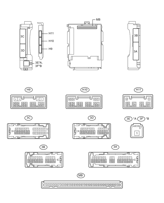
*A for LHD *B for RHD
-
Disconnect the MB main body ECU (multiplex network body ECU) connectors.
-
Measure the voltage and resistance according to the value(s) in the table below.
Tech Tips
Measure the values on the wire harness side with the connectors disconnected.
Terminal No. (Symbol) Wiring Color Terminal Description Condition Specified Condition MB-11(GND1) - Body ground - Ground Always Below 1 Ω MB-29 (ACC) - Body ground - ACC power supply Engine switch on (ACC) 11 to 14 V Engine switch off Below 1 V MB-30 (BECU) - Body ground - Battery power supply Always 11 to 14 V MB-31 (ALTB) - Body ground - Battery power supply Always 11 to 14 V MB-32 (IG) - Body ground - IG power supply Engine switch on (IG) 11 to 14 V Engine switch off Below 1 V -
Reconnect the MB main body ECU (multiplex network body ECU) connector.
-
Measure the voltage and check for pulses according to the value(s) in the table below.
Terminal No. (Symbol) Wiring Color Terminal Description Condition Specified Condition H9-11 (TMSW) - Body ground LG - Body ground Luggage door opening cancel switch signal Luggage door opening cancel switch on Below 1 V Engine switch off, all doors closed and luggage door opening cancel switch off Pulse generation H9-5 (TSW) - Body ground R - Body ground Luggage door opening switch signal Luggage door opening switch on Below 1 V Engine switch off, all doors closed and luggage door opening switch off Pulse generation
-
-
CHECK LUGGAGE CLOSER MOTOR ASSEMBLY

-
Disconnect the U16 luggage closer motor assembly connector.
-
Measure the resistance and voltage according to the value(s) in the table below.
Tech Tips
Measure the values on the wire harness side with the connectors disconnected.
Terminal No. (Symbol) Wiring Color Terminal Description Condition Specified Condition U16-8 (IG) - U16-11 (GND) GR - W-B IG power supply Engine switch on (IG) 11 to 14 V Engine switch off Below 1 V U16-10 (ECUB) - U16-11 (GND) W - W-B ECU power supply Always 11 to 14 V U16-11 (GND) - Body ground W-B - Body ground Ground Always Below 1 Ω U16-12 (B) - U16-11 (GND) B - W-B Battery power supply Always 11 to 14 V -
Reconnect the U16 luggage closer motor assembly connector.
-
Measure the voltage and check for pulses according to the value(s) in the table below.
Terminal No. (Symbol) Wiring Color Terminal Description Condition Specified Condition U16-1 (LCM-) - U16-11 (GND) L - W-B Luggage compartment door closer motor output signal Luggage compartment door closer is operated 11 to 14 V U16-2 (LCM+) - U16-11 (GND) LG - W-B Luggage compartment door closer motor output signal Luggage compartment door closer is operated in reverse 11 to 14 V U16-4 (LDDN) - U16-11 (GND) GR - W-B Door control switch input signal Door control switch is on Below 1 V Engine switch on (IG), luggage compartment door closed and door control switch is OFF Pulse generation U16-7 (HAF) - U16-11 (GND) V - W-B Luggage compartment door closer half latch switch input signal Engine switch on (IG), luggage compartment door open → fully closed Below 1 V → Pulse generation U16-20 (PAWL) - U16-11 (GND) P - W-B Luggage compartment door closer pawl switch input signal Engine switch on (IG), luggage compartment door open → fully closed Below 1 V → Pulse generation
-
-
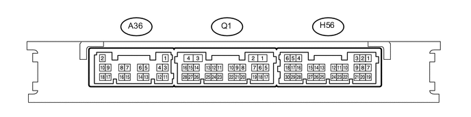
CHECK CERTIFICATION ECU (SMART KEY ECU ASSEMBLY)
-
Disconnect the A36 certification ECU (smart key ECU assembly) connector.
-
Measure the resistance and voltage according to the value(s) in the table below.
Tech Tips
Measure the values on the wire harness side with the connectors disconnected.
Terminal No. (Symbol) Wiring Color Terminal Description Condition Specified Condition A36-2 (+B) - Body ground W - Body ground Battery power supply Always 11 to 14 V A36-10 (CUTB) - Body ground L - Body ground Dark current cut fuse pin input signal Always 11 to 14 V A36-11 (E) - Body ground W-B - Body ground Ground Always Below 1 Ω -
Reconnect the A36 certification ECU (smart key ECU assembly) connector.
-
Measure the voltage according to the value(s) in the table below.
Terminal No. (Symbol) Wiring Color Terminal Description Condition Specified Condition H56-5 (IG) - Body ground LG - Body ground Ignition power supply Engine switch off Below 1 V Engine switch on (IG) 11 to 14 V Q1-27 (TSW5) - A36-11 (E) LG - W-B Luggage electrical key switch input signal Engine switch on (IG), luggage compartment door is fully closed and luggage electrical key switch off Pulse generation
-