INSTRUMENT PANEL SAFETY PAD REASSEMBLY
PROCEDURE
-
INSTALL NO. 1 INSTRUMENT PANEL BRACKET
-
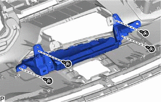
Install the No. 1 instrument panel bracket with the 4 screws <E>.
-
-
INSTALL NO. 2 INSTRUMENT PANEL BRACKET
-
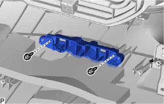
Install the No. 2 instrument panel bracket with the 2 screws <E>.
-
-
INSTALL NO. 1 INSTRUMENT PANEL PIN
-
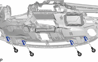
Install the 4 No. 1 instrument panel pins with the 4 screws <E>.
-
-
INSTALL NO. 2 SIDE DEFROSTER NOZZLE
-
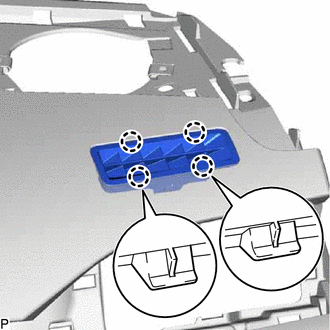
Engage the 4 claws to install the No. 2 side defroster nozzle.
-
-
INSTALL NO. 1 SIDE DEFROSTER NOZZLE
-
Engage the 4 claws to install the No. 1 side defroster nozzle.
-
-
INSTALL NO. 1 ION GENERATOR BRACKET (w/ Ion Generator)
-
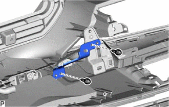
Install the No. 1 ion generator bracket with the 2 screws <D>.
-
-
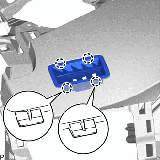
INSTALL NO. 2 ION GENERATOR BRACKET (w/ Ion Generator)
-
Install the No. 2 ion generator bracket and No. 6 heater to register duct with the screw <D>.
-
-
INSTALL NO. 3 INSTRUMENT PANEL WIRE
-
for LHD:
-
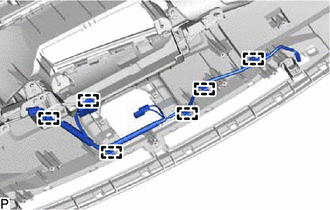
Engage the 6 clamps to install the No. 3 instrument panel wire.
-
-
for RHD:
-
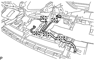
Engage the 5 clamps to install the No. 3 instrument panel wire.
-
-
-
INSTALL NAVIGATION ANTENNA ASSEMBLY (w/ Navigation System)
-
INSTALL ANTENNA CORD SUB-ASSEMBLY (for LHD)
-
INSTALL ANTENNA CORD SUB-ASSEMBLY (for RHD)
-
INSTALL INSTRUMENT PANEL PASSENGER AIRBAG ASSEMBLY
-
INSTALL NO. 3 HEATER TO REGISTER DUCT
-
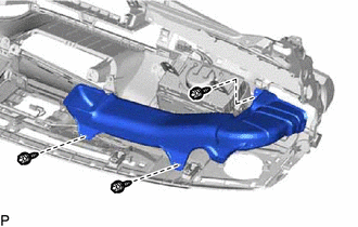
Install the No. 3 heater to register duct with the 3 screws <D>.
-
-
INSTALL NO. 1 HEATER TO REGISTER DUCT
-
w/o Ion Generator:
-
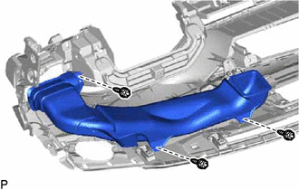
Install the No. 1 heater to register duct with the 3 screws <D>.
-
-
w/ Ion Generator:
-
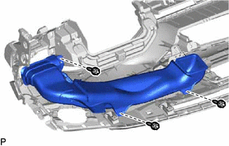
Engage the No. 1 heater to register duct to the No. 6 heater to register duct to install it.
-
Install the 3 screws <D>.
-
-
-
INSTALL DEFROSTER NOZZLE ASSEMBLY
-
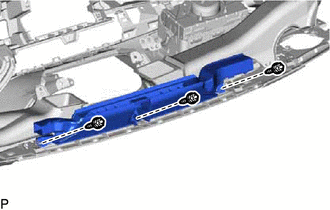
Install the defroster nozzle assembly with the 3 screws <D>.
-
-
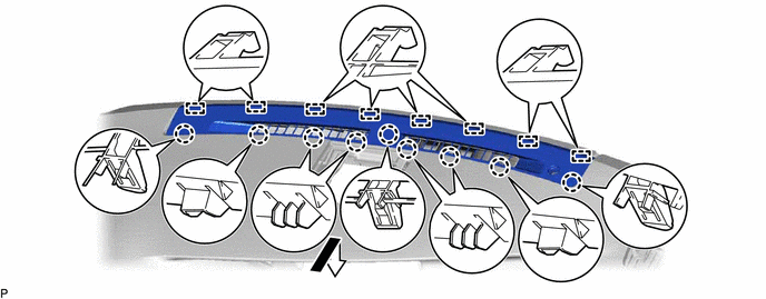
INSTALL NO. 1 DEFROSTER NOZZLE GARNISH
-
Engage the 8 guides and 9 claws to install the No. 1 defroster nozzle garnish as shown in the illustration.
-
-
INSTALL AUTOMATIC LIGHT CONTROL SENSOR
-
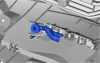
INSTALL NO. 2 SIDE DEFROSTER NOZZLE DUCT
-
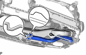
Engage the 2 claws.
-
Install the No. 2 side defroster nozzle duct with the screw <D>.
-
-
INSTALL NO. 1 SIDE DEFROSTER NOZZLE DUCT
-
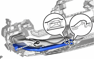
Engage the 2 claws.
-
Install the No. 1 side defroster nozzle duct with the screw <D>.
-