CLIMATE CONTROL SEAT SYSTEM Climate Control Seat System does not Operate
DESCRIPTION
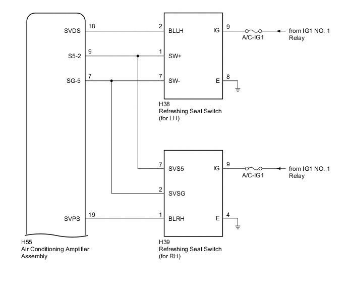
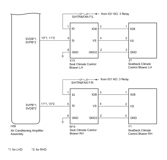
The air conditioning amplifier assembly receives refreshing seat switch position signals when the engine switch is on (IG), and then transmits airflow amount signals to each seat climate blower.
WIRING DIAGRAM
CAUTION / NOTICE / HINT
Note
Inspect the fuses for circuits related to this system before performing the following inspection procedure.
PROCEDURE
-
CHECK CLIMATE CONTROL SEAT OPERATION
-
Check the climate control seat operation Click here.
Result Result Proceed to Climate control seat does not operate (for LH) A Climate control seat does not operate (for RH) B Both climate control seats do not operate C
B 
CHECK CLIMATE CONTROL SEAT OPERATION Click here
C
CHECK AIR CONDITIONING SYSTEM Click here
A 
-
-
CHECK CLIMATE CONTROL SEAT OPERATION
-
Check the climate control seat operation again Click here.
Result Result Proceed to Only seatback climate control blower LH does not operate A Only seat climate control blower LH does not operate B Both climate control blowers do not operate C
B 
REPLACE SEAT CLIMATE CONTROL BLOWER LH Click here
C
CHECK HARNESS AND CONNECTOR (BATTERY - SEAT CLIMATE CONTROL BLOWER LH - BODY GROUND) Click here
A
-
-
CHECK HARNESS AND CONNECTOR (SEAT CLIMATE CONTROL BLOWER LH - SEATBACK CLIMATE CONTROL BLOWER LH)
-
Disconnect the Z1 seatback climate control blower LH connector.
-
Disconnect the X15 seat climate control blower LH connector.
-
Measure the resistance according to the value(s) in the table below.
Standard Resistance Tester Connection Condition Specified Condition Z1-1 (IGB) - X15-3 (IGB) Always Below 1 Ω Z1-1 (IGB) - Body ground Always 10 kΩ or higher Z1-2 (VS) - X15-4 (VS) Always Below 1 Ω Z1-2 (VS) - Body ground Always 10 kΩ or higher Z1-3 (GND) - X15-2 (GND2) Always Below 1 Ω Z1-3 (GND) - Body ground Always 10 kΩ or higher
NG
REPAIR OR REPLACE HARNESS OR CONNECTOR
OK
-
-
REPLACE SEATBACK CLIMATE CONTROL BLOWER LH
-
Replace the seatback climate control blower LH Click here.
NEXT
-
-
CHECK CLIMATE CONTROL SEAT OPERATION
-
Check the climate control seat operation Click here.
OK The climate control seat operates normally.
OK
END (SEATBACK CLIMATE CONTROL BLOWER LH WAS DEFECTIVE)
NG
REPLACE SEAT CLIMATE CONTROL BLOWER LH Click here
-
-
CHECK HARNESS AND CONNECTOR (BATTERY - SEAT CLIMATE CONTROL BLOWER LH - BODY GROUND)
-
Disconnect the X15 seat climate control blower LH connector.
-
Measure the voltage and resistance according to the value(s) in the table below.
Standard Voltage Tester Connection Condition Specified Condition X15-1 (IG) - Body ground Engine switch on (IG) 11 to 14 V Standard Resistance Tester Connection Condition Specified Condition X15-6 (GND) - Body ground Always Below 1 Ω
NG
REPAIR OR REPLACE HARNESS OR CONNECTOR
OK
-
-
CHECK HARNESS AND CONNECTOR (SEAT CLIMATE CONTROL BLOWER LH - AIR CONDITIONING AMPLIFIER ASSEMBLY)
-
Disconnect the H55 air conditioning amplifier assembly connector.
-
Measure the resistance according to the value(s) in the table below.
Standard Resistance for LHD Tester Connection Condition Specified Condition X15-5 (SI) - H55-10 (SVDB) Always Below 1 Ω X15-5 (SI) - Body ground Always 10 kΩ or higher for RHD Tester Connection Condition Specified Condition X15-5 (SI) - H55-11 (SVPB) Always Below 1 Ω X15-5 (SI) - Body ground Always 10 kΩ or higher
NG
REPAIR OR REPLACE HARNESS OR CONNECTOR
OK
-
-
CHECK AIR CONDITIONING AMPLIFIER ASSEMBLY
-
Reconnect the H55 air conditioning amplifier assembly connector.
-
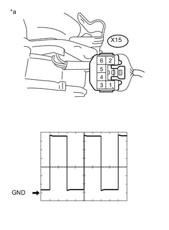
Text in Illustration *a Component with harness connected
(Seat Climate Control Blower LH)
Reconnect the X15 seat climate control blower LH connector.
-
Check the input signal waveform.
-
Connect an oscilloscope to terminal 3 and body ground with the seat climate control blower LH connector still connected.
-
Check the signal waveform according to the condition(s) in the table below.
Terminal No. X15-5 (SI) - Body ground Tool Setting 1 V/DIV., 1 msec/DIV. Vehicle Condition Engine switch on (IG), refreshing seat switch (for LH) on
(blower position)
OK Waveform is similar to that shown in the illustration.
-
OK
REPLACE SEAT CLIMATE CONTROL BLOWER LH Click here
NG
-
-
INSPECT REFRESHING SEAT SWITCH (FOR LH)
-
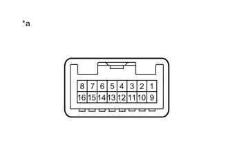
Text in Illustration *a Component without harness connected
(Refreshing Seat Switch (for LH))
Remove the refreshing seat switch (for LH) Click here.
-
Measure the resistance according to the value(s) in the table below.
Standard Resistance Tester Connection Condition Specified Condition 1 - 7 Always 1.54 to 2.86 kΩ 2 - 7 Refreshing seat switch (for LH) off 10 kΩ or higher 2 - 7 Refreshing seat switch (for LH) on (Vol: 3)
(blower position)
38.5 to 71.5 Ω
NG
REPLACE REFRESHING SEAT SWITCH (FOR LH) Click here
OK
-
-
CHECK HARNESS AND CONNECTOR (REFRESHING SEAT SWITCH (FOR LH) - AIR CONDITIONING AMPLIFIER ASSEMBLY)
-
Disconnect the H55 air conditioning amplifier assembly connector.
-
Measure the resistance according to the value(s) in the table below.
Standard Resistance Tester Connection Condition Specified Condition H38-2 (BLLH) - H55-18 (SVDS) Always Below 1 Ω H38-2 (BLLH) - Body ground Always 10 kΩ or higher H38-1 (SW+) - H55-9 (S5-2) Always Below 1 Ω H38-1 (SW+) - Body ground Always 10 kΩ or higher H38-7 (SW-) - H55-7 (SG-5) Always Below 1 Ω H38-7 (SW-) - Body ground Always 10 kΩ or higher
OK
REPLACE AIR CONDITIONING AMPLIFIER ASSEMBLY Click here
NG
REPAIR OR REPLACE HARNESS OR CONNECTOR
-
-
CHECK CLIMATE CONTROL SEAT OPERATION
-
Check the climate control seat operation again Click here.
Result Result Proceed to Only seatback climate control blower RH does not operate A Only seat climate control blower RH does not operate B Both climate control blowers do not operate C
B
REPLACE SEAT CLIMATE CONTROL BLOWER RH Click here
C
CHECK HARNESS AND CONNECTOR (BATTERY - SEAT CLIMATE CONTROL BLOWER RH - BODY GROUND) Click here
A
-
-
CHECK HARNESS AND CONNECTOR (SEAT CLIMATE CONTROL BLOWER RH - SEATBACK CLIMATE CONTROL BLOWER RH)
-
Disconnect the Y1 seatback climate control blower RH connector.
-
Disconnect the W14 seat climate control blower RH connector.
-
Measure the resistance according to the value(s) in the table below.
Standard Resistance Tester Connection Condition Specified Condition Y1-1 (IGB) - W14-3 (IGB) Always Below 1 Ω Y1-1 (IGB) - Body ground Always 10 kΩ or higher Y1-2 (VS) - W14-4 (VS) Always Below 1 Ω Y1-2 (VS) - Body ground Always 10 kΩ or higher Y1-3 (GND) - W14-2 (GND2) Always Below 1 Ω Y1-3 (GND) - Body ground Always 10 kΩ or higher
NG
REPAIR OR REPLACE HARNESS OR CONNECTOR
OK
-
-
REPLACE SEATBACK CLIMATE CONTROL BLOWER RH
-
Replace the seatback climate control blower RH Click here.
NEXT
-
-
CHECK CLIMATE CONTROL SEAT OPERATION
-
Check the climate control operation again Click here.
OK The climate control seat operates normally.
OK
END (SEATBACK CLIMATE CONTROL BLOWER RH WAS DEFECTIVE)
NG
REPLACE SEAT CLIMATE CONTROL BLOWER RH Click here
-
-
CHECK HARNESS AND CONNECTOR (BATTERY - SEAT CLIMATE CONTROL BLOWER RH - BODY GROUND)
-
Disconnect the W14 seat climate control blower RH connector.
-
Measure the voltage and resistance according to the value(s) in the table below.
Standard Voltage Tester Connection Condition Specified Condition W14-1 (IG) - Body ground Engine switch on (IG) 11 to 14 V Standard Resistance Tester Connection Condition Specified Condition W14-6 (GND) - Body ground Always Below 1 Ω
NG
REPAIR OR REPLACE HARNESS OR CONNECTOR
OK
-
-
CHECK HARNESS AND CONNECTOR (SEAT CLIMATE CONTROL BLOWER RH - AIR CONDITIONING AMPLIFIER ASSEMBLY)
-
Disconnect the H55 air conditioning amplifier assembly connector.
-
Measure the resistance according to the value(s) in the table below.
Standard Resistance for LHD Tester Connection Condition Specified Condition W14-5 (SI) - H55-11 (SVPB) Always Below 1 Ω W14-5 (SI) - Body ground Always 10 kΩ or higher for RHD Tester Connection Condition Specified Condition W14-5 (SI) - H55-10 (SVDB) Always Below 1 Ω W14-5 (SI) - Body ground Always 10 kΩ or higher
NG
REPAIR OR REPLACE HARNESS OR CONNECTOR
OK
-
-
CHECK AIR CONDITIONING AMPLIFIER ASSEMBLY
-
Reconnect the H55 air conditioning amplifier assembly connector.
-
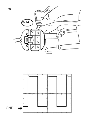
Text in Illustration *a Component with harness connected
(Seat Climate Control Blower RH)
Reconnect the W14 seat climate control blower RH connector.
-
Check the input signal waveform.
-
Connect an oscilloscope to terminal 3 and body ground with the seat climate control blower RH connector still connected.
-
Check the signal waveform according to the condition(s) in the table below.
Terminal No. W14-5 (SI) - Body ground Tool Setting 1 V/DIV., 1 msec/DIV. Vehicle Condition Engine switch on (IG), refreshing seat switch (for RH) on
(blower position)
OK Waveform is similar to that shown in the illustration.
-
OK
REPLACE SEAT CLIMATE CONTROL BLOWER RH Click here
NG
-
-
INSPECT REFRESHING SEAT SWITCH (FOR RH)
-
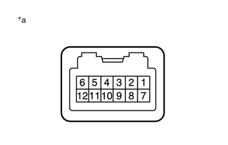
Text in Illustration *a Component without harness connected
(Refreshing Seat Switch (for RH))
Remove the refreshing seat switch (for RH) Click here.
-
Measure the resistance according to the value(s) in the table below.
Standard Resistance Tester Connection Condition Specified Condition 2 - 7 Always 1.54 to 2.86 kΩ 1 - 2 Refreshing seat switch (for RH) off 10 kΩ or higher 1 - 2 Refreshing seat switch (for RH) on (Vol: 3)
(blower position)
38.5 to 71.5 Ω
NG
REPLACE REFRESHING SEAT SWITCH (FOR RH) Click here
OK
-
-
CHECK HARNESS AND CONNECTOR (REFRESHING SEAT SWITCH (FOR RH) - AIR CONDITIONING AMPLIFIER ASSEMBLY)
-
Disconnect the H55 air conditioning amplifier assembly connector.
-
Measure the resistance according to the value(s) in the table below.
Standard Resistance Tester Connection Condition Specified Condition H39-7 (SVS5) - H55-9 (S5-2) Always Below 1 Ω H39-7 (SVS5) - Body ground Always 10 kΩ or higher H39-1 (BLRH) - H55-19 (SVPS) Always Below 1 Ω H39-1 (BLRH) - Body ground Always 10 kΩ or higher H39-2 (SVSG) - H55-7 (SG-5) Always Below 1 Ω H39-2 (SVSG) - Body ground Always 10 kΩ or higher
OK
REPLACE AIR CONDITIONING AMPLIFIER ASSEMBLY Click here
NG
REPAIR OR REPLACE HARNESS OR CONNECTOR
-
-
CHECK AIR CONDITIONING SYSTEM
-
Check the air conditioning system.
OK The air conditioning system operates normally.
NG
GO TO AIR CONDITIONING SYSTEM Click here
OK
-
-
CHECK HARNESS AND CONNECTOR (REFRESHING SEAT SWITCH (FOR LH) - AIR CONDITIONING AMPLIFIER ASSEMBLY)
-
Disconnect the H38 refreshing seat switch (for LH) connector.
-
Disconnect the H55 air conditioning amplifier assembly connector.
-
Measure the resistance according to the value(s) in the table below.
Standard Resistance Tester Connection Condition Specified Condition H38-1 (SW+) - H55-9 (S5-2) Always Below 1 Ω H38-1 (SW+) - Body ground Always 10 kΩ or higher H38-7 (SW-) - H55-7 (SG-5) Always Below 1 Ω H38-7 (SW-) - Body ground Always 10 kΩ or higher
OK
REPLACE AIR CONDITIONING AMPLIFIER ASSEMBLY Click here
NG
REPAIR OR REPLACE HARNESS OR CONNECTOR
-