BODY STRUCTURE
-
FUNCTION
-
Safety Features
-
Impact Absorbing Structure for Frontal Collision
-
Through the adoption of a body structure that disperses collision energy to multiple frame components, collision energy is efficiently absorbed to suppress cabin deformation.
-
The front side members and apron upper members are utilized to absorb and disperse energy in a frontal collision.
-
The apron upper members have been strengthened to optimize dispersal of collision energy to the front pillar reinforcement, beltline reinforcement, rocker panel reinforcement and floor panel.
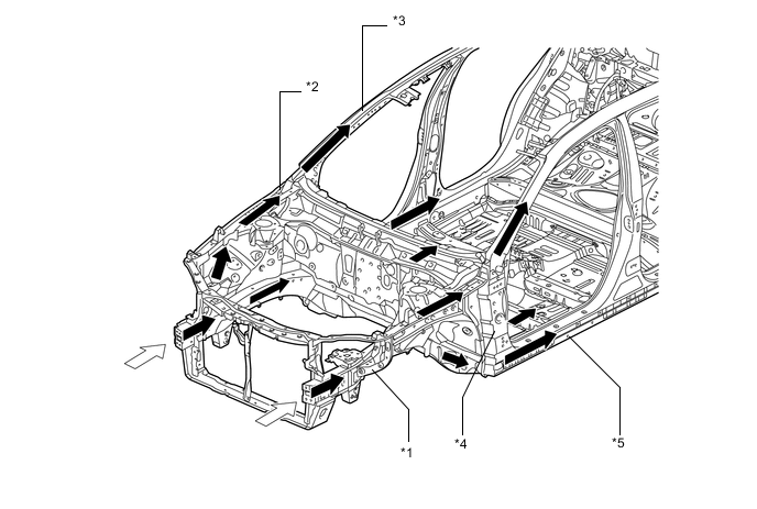
Text in Illustration *1 Front Side Member *2 Apron Upper Member *3 Front Pillar Reinforcement *4 Beltline Reinforcement *5 Rocker Panel Reinforcement - - 
Impact 
Impact Flow -
The rocker panel reinforcements have been strengthened to optimize dispersal of collision energy from the front wheels to the beltline reinforcement, front pillar reinforcement and floor panel.
-
The front end of the rocker is has been extended further forward. Therefore, impact force during a frontal collision can be absorbed at the front end of the rocker, suppressing vehicle body deformation around the cabin. (on Right Side of RHD Models)
-
By installing an A-pillar lower patch, vehicle body deformation around the cabin caused by impact force during a frontal collision is suppressed. (on Right Side of RHD Models)
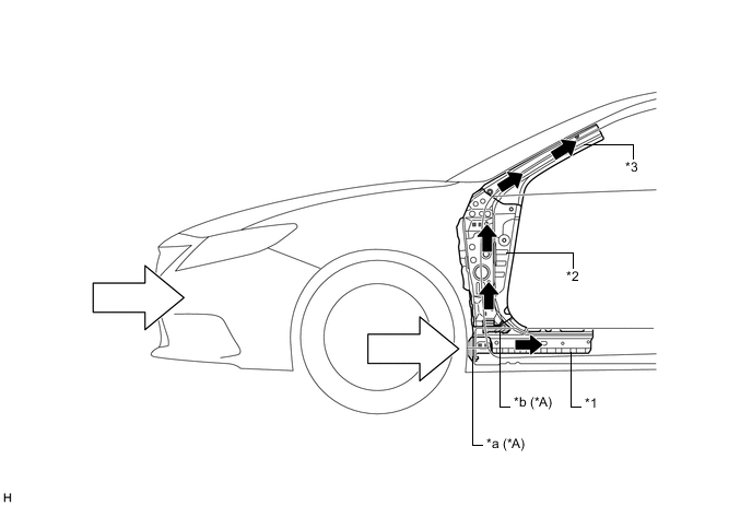
Text in Illustration *A Right Side of RHD Models - - *1 Rocker Panel Reinforcement *2 Beltline Reinforcement *3 Front Pillar Reinforcement - - *a Extra Piece *b A-pillar Lower Patch Impact Impact Flow
-
-
Impact Absorbing Structure for Side Collision
-
Through the adoption of a body structure that disperses collision energy to multiple frame components, collision energy is efficiently absorbed to suppress cabin deformation.
-
The center pillars are strengthened to optimize dispersal of collision energy to the floor crossmember and roof reinforcement.
-
The use of roof reinforcements and floor crossmembers enables a construction that transmits load to the opposite side of the vehicle in a collision.
-
Ultra high strength sheet steel is used for the center pillar outer reinforcement and center pillar hinge reinforcement to ensure high strength.
-
Optimal placement of the impact protect beams enables a construction that efficiently transmits load.
-
A rear door box is provided inside the bottom of the rear door. In the event of a side collision, the rear door box strikes the rear crossmember gusset, absorbing the impact by transmitting it to the center floor member.
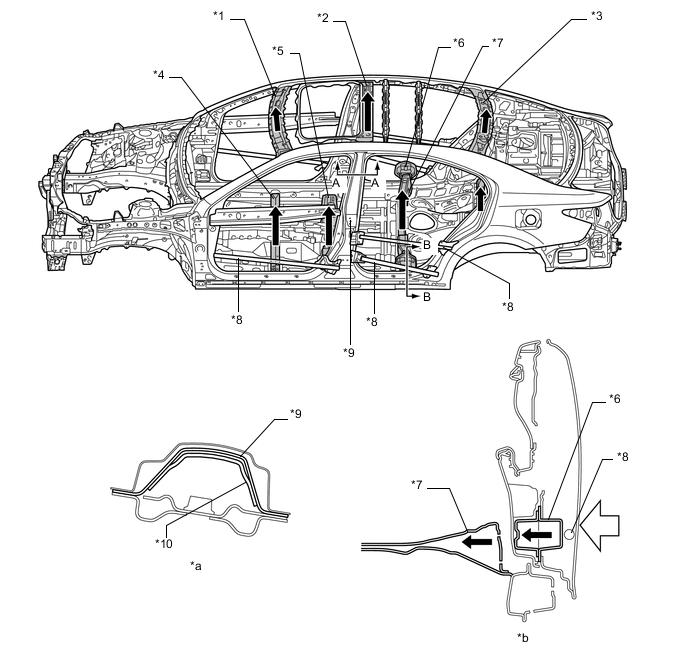
Text in Illustration *1 Front Header Extension *2 Roof Center Reinforcement *3 Roof Rear Reinforcement *4 Front Floor Crossmember *5 Center Floor Crossmember *6 Rear Door Box *7 Center Floor Crossmember Gusset *8 Impact Protect Beam *9 Center Pillar Outer Reinforcement *10 Center Pillar Hinge Reinforcement *a A-A Cross Section *b B-B Cross Section Impact Impact Flow -
When the roof is subjected to an impact, the impact is dispersed to the roof reinforcements, front pillars and center pillars, thereby minimizing deformation of the cabin.
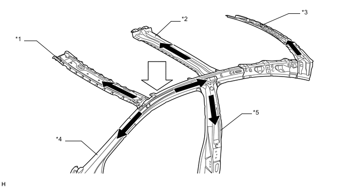
Text in Illustration *1 Front Header Extension *2 Roof Center Reinforcement *3 Roof Rear Reinforcement *4 Front Pillar *5 Center Pillar - - Impact Impact Flow
-
-
Lessening Pedestrian Injury
-
A longitudinal ribbed structure is adopted for the inner hood to cushion impact.
-
A hood reinforcement is provided for the hood inner panel to help secure excellent pedestrian protection performance and tensile rigidity.
-
The space between the hood panel and the hood reinforcement lock striker has been formed into a crushable structure so that the hood sub-assembly can collapse easily during a collision.
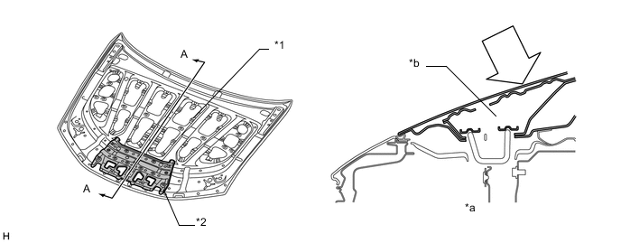
Text in Illustration *1 Longitudinal Ribbed Structure *2 Hood Reinforcement (Impact Absorbing Structure) *a A-A Cross Section *b Space Impact - - -
The cowl uses an open section structure that collapses easily in an impact from the top, thus reducing the impact to and head injuries sustained by a pedestrian in an accident.
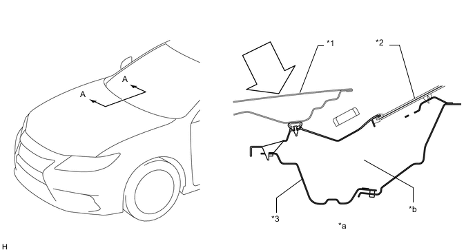
Text in Illustration *1 Hood Panel *2 Windshield Glass *3 Cowl Top Panel Sub-assembly - - *a A-A Cross Section *b Open Section Impact - -
-
-
-
Aerodynamics
-
An aero stabilizing fin is provided on the driver door, front passenger door and rear combination lenses for enhanced aerodynamics.
-
After passing the aero stabilizing fin, the air speed will increase and vortex flow will be generated.
-
This vortex increases the speed of the surrounding air while at the same time pulling the airflow towards the vehicle body.
-
The airflow with higher speed passes near both sides of the vehicle body and ends at the rear of the vehicle. This helps to hold the vehicle body, and a vortex will be generated.
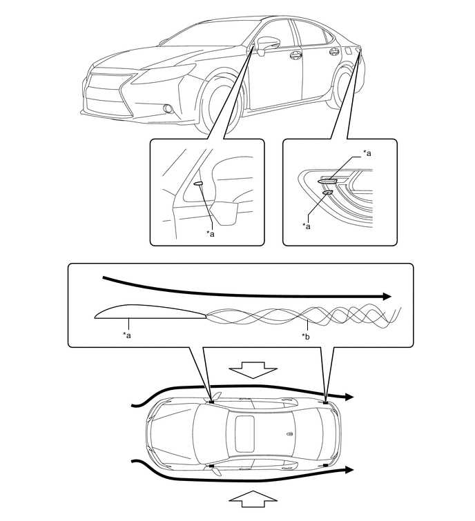
Text in Illustration *a Aero Stabilizing Fin *b Vortex Airflow Hold the Vehicle from Both Sides -
-
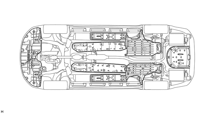
A fin-shaped engine under cover and rear under cover have been adopted to achieve higher diffuser efficiency, thereby ensuring stability.
-
-
-
CONSTRUCTION
-
Lightweight and Highly Rigid Body
-
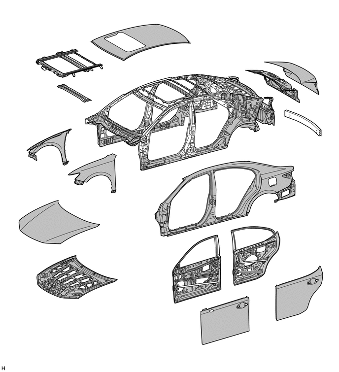
High strength steel and ultra high strength steel are used in order to realize excellent body rigidity and a lightweight body.
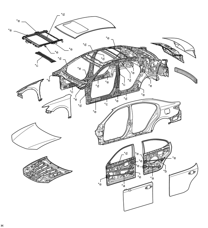
Text in Illustration *a Ultra High Strength Steel (1620 MPa Class) *b Ultra High Strength Steel (1470 MPa Class) *c Ultra High Strength Steel (980 MPa Class) *d High Strength Steel (590 MPa Class) *e High Strength Steel (440 MPa Class) - - 
Ultra High Strength Sheet Steel 
High Strength Sheet Steel 
Aluminum - -
-
-
Rust Resistant Body
-
Anti-corrosion sheet steel is used as shown in the following illustration:
Text in Illustration Anti-corrosion Sheet Steel - - -
For rust resistance, sealant has been applied to the floor panel to prevent water from entering through the mating surfaces of the panels. Undercoating has been also applied to reduce damage to the body from chipping, contributing to rust resistance.
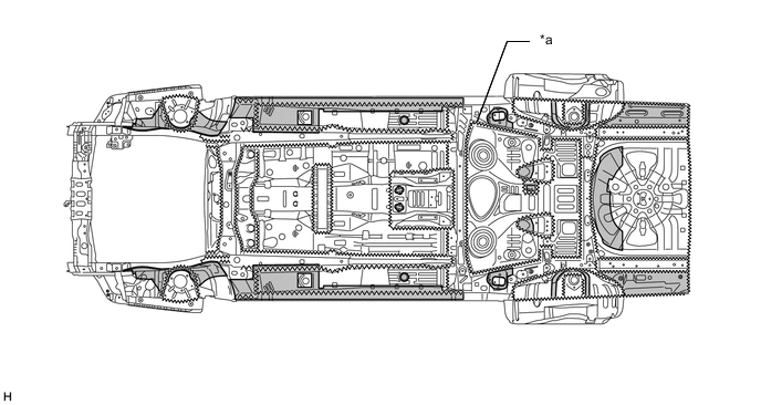
Text in Illustration *a Sealant - - Undercoat - -
-
-
Body Shell Construction
-
The cowl top panel sub-assembly outer, which is straight, is used to connect the left and right front spring supports, improving lateral rigidity and ensuring front suspension input point rigidity and body rigidity.
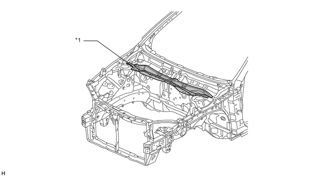
Text in Illustration *1 Cowl Top Panel Sub-assembly - - -
A closed shape has been adopted for the upper back panel. The upper back panel, which is straight, is used to connect the left and right back side panels, promoting a lightweight yet rigid body.
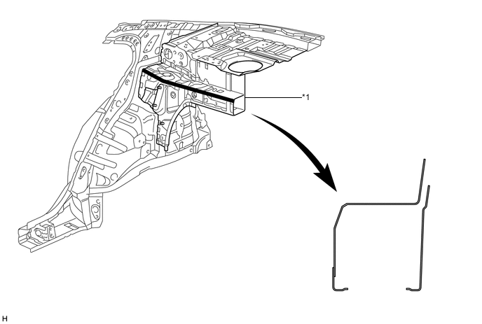
Text in Illustration *1 Upper Back Panel - - -
Reinforcements have been added to the open area of the lower back panel, ensuring torsional rigidity and excellent handling stability.
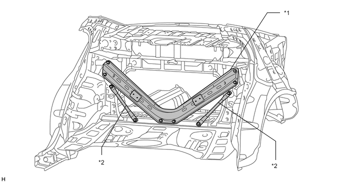
Text in Illustration *1 Lower Back Panel Reinforcement Sub-assembly *2 Lower Back Panel Reinforcement Sub-assembly No. 2
-
-
Anti-chipping Application
-
To help prevent the paint from the paint from chipping, anti-chipping paint is applied to the hood panel.
-
Anti-chipping tape is applied to the quarter panel on the back of the rear door to protect the paint surface from icy snow or gravel and to achieve a high level of rust resistance.
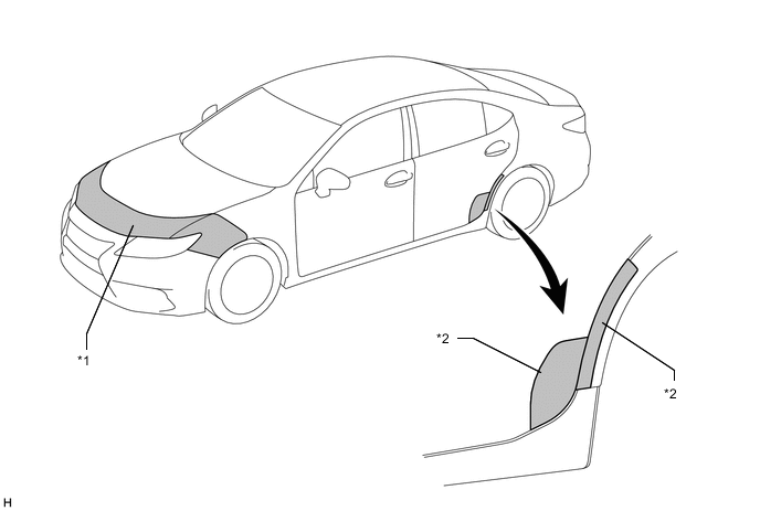
Text in Illustration *1 Anti-chipping Paint *2 Anti-chipping Tape
-
-
Low Vibration and Low Noise Body
-
A hood insulator is provided on the underside of the hood panel. This achieves excellent sound insulation performance.
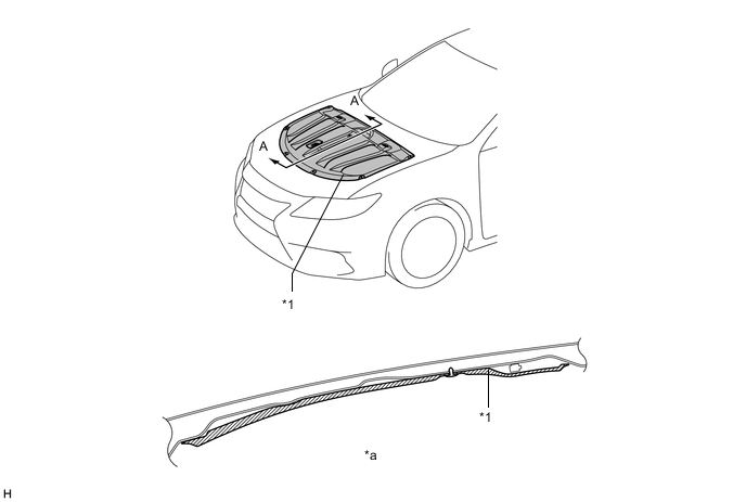
Text in Illustration *1 Hood Insulator - - *a A-A Cross Section - - -
Sound absorbing material (front fender seal) is used in the front fender liner to reduce road noise.
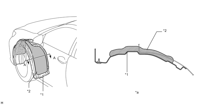
Text in Illustration *1 Front Fender Liner *2 Sound-absorbing Material (Front Fender Seal) *a A-A Cross Section - - -
A front fender upper protector is used on the engine compartment side of the fender side cover to reduce the amount of noise transmitted from the area between the fender and apron to the vehicle cabin.
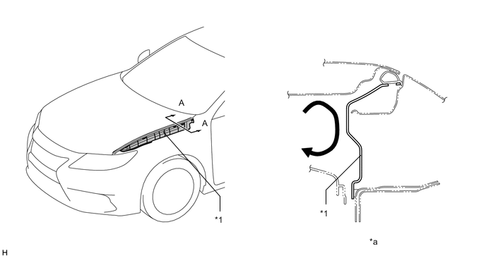
Text in Illustration *1 Front Fender Upper Protector - - *a A-A Cross Section - - Noise - - -
A front fender side panel protector is used to reduce the amount of noise transmitted from the area between the fender and front pillar to the vehicle cabin.
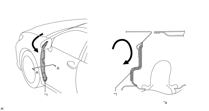
Text in Illustration *1 Front Fender Side Panel Protector - - *a A-A Cross Section - - Noise - - -
Damping coatings are provided, combining enhanced quietness and reduced weight.
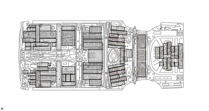
Text in Illustration Damping Material Area - - -
The layout of the sound-absorbing material is optimized to reduce noise and vibration.
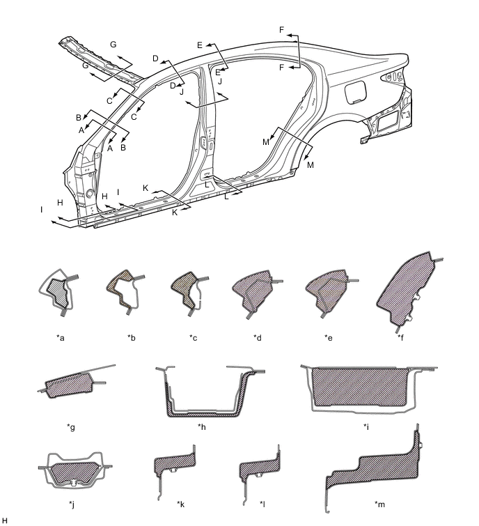
Text in Illustration *a A-A Cross Section *b B-B Cross Section *c C-C Cross Section *d D-D Cross Section *e E-E Cross Section *f F-F Cross Section *g G-G Cross Section *h H-H Cross Section *i I-I Cross Section *j J-J Cross Section *k K-K Cross Section *l L-L Cross Section *m M-M Cross Section - - Sound-absorbing Material - -
-
-