STOP AND START
-
FUNCTION OF MAIN COMPONENTS
Component Function Engine Stop and Start ECU Sends either an engine stop or restart signal to the ECM according to the signals from each sensor and switch. Engine Stop and Start ECU Backup Boost Converter
-
Supplies battery voltage to help make up for the voltage drop that occurs when the engine is restarted, preventing the operation of various systems from being interrupted due to low battery voltage.
-
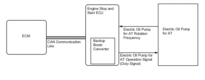
Supplies battery voltage to the electric oil pump for AT.
Park/Neutral Position Switch Assembly Detects whether the shift lever position is in park/neutral and sends a signal to the engine stop and start ECU. Brake Booster Assembly Vacuum Sensor Assembly Detects the brake booster vacuum pressure and sends a signal to the engine stop and start ECU via the ECM. Hood Lock Assembly Engine Hood Courtesy Switch Detects whether the hood is open or closed and sends a signal to the engine stop and start ECU. Front Door Courtesy Light Switch Assembly (LH) Detects whether the driver door is open or closed and sends a signal to the engine stop and start ECU via the main body ECU (multiplex network body ECU) via CAN communication. Front Seat Inner Belt Assembly LH Front Seat Belt Buckle Switch Detects whether or not the driver's seat belt has been fastened, and sends a signal to the engine stop and start ECU via the main body ECU (multiplex network body ECU) via CAN communication. Ambient Temperature Sensor (Thermistor Assembly) Detects the ambient temperature and sends a signal to the engine stop and start ECU via the combination meter assembly. Air Conditioning Amplifier Assembly Sends the outside temperature signal and engine restart signal to the engine stop and start ECU. Combination Meter Assembly Stop and Start Indicator Light
-
Turns on when the engine is stopped due to stop and start system control.
-
Blinks to inform the driver that the idling stop is canceled and the engine will restart when the driver door is opened during idling stop.
Stop and Start Cancel Indicator Light
-
Turns on to inform the driver that the system has been disabled when stop and start system operation is prohibited by the stop and start cancel switch.
-
If a system malfunction is detected, the stop and start cancel indicator light blinks to inform the driver.
Multi-information Display
-
Displays the amount of time idling stop was performed since the engine switch was turned to on (IG) to when the engine switch was turned off and the amount of time idling stop was performed since the reset switch was last pressed.
-
Displays the settings of the stop and start system or warning information, etc.
Integration Control and Panel Assembly Stop and Start Cancel Switch Operation of the system can be canceled by pressing the stop and start cancel switch. Pressing the switch again or turning the power source off and back on restores the operation of the system. ECM
-
Sends various information about engine conditions to the engine stop and start ECU.
-
Based on signals from the battery sensor (battery state sensor assembly), determines whether the battery installed on the vehicle is a specified or non-specified battery, and sends the determination result to the engine stop and start ECU.
Brake Actuator Assembly Skid Control ECU Sends a vehicle speed signal to the engine stop and start ECU. Airbag Sensor Assembly Sends airbag deployment information in the event of a collision and a deceleration signal to the engine stop and start ECU. Main Body ECU (Multiplex Network Body ECU) Sends a front door courtesy light switch assembly signal and front seat belt buckle switch LH signal to the engine stop and start ECU. Power Steering ECU Assembly Sends an electrical power steering assist signal to the engine stop and start ECU. Electric Oil Pump for AT Holds the AT oil pressure during idle stop. Battery Sensor (Battery State Sensor Assembly) Detects the battery charging and discharging amount and sends a signal to the ECM. Stop Light Switch Assembly Detects a brake pedal released condition and sends a signal to the engine stop and start ECU via the ECM. Accelerator Pedal Sensor Assembly Detects an accelerator pedal opening angle and sends a signal to the engine stop and start ECU via the ECM. Crank Position Sensor Detects the crankshaft angle when the engine is stopped and sends this information to the ECM. Transmission Valve Body Assembly ATF Temperature Sensor Detects the ATF temperature. Engine Coolant Temperature Sensor Sends the coolant temperature to the engine stop and start ECU via the ECM. Generator Assembly Sends the generator assembly generation condition to the engine stop and start ECU via the ECM. -
-
FUNCTION
-
Stop and Start System Function Setting
-
Using the steering pad switch on the steering pad switch assembly and the multi-information display on the combination meter assembly, the engine stop operation time due to stop and start control when the air conditioning system is on can be changed between NORMAL and LONG (the stop and start system has priority).
-
-
Stop and Start System Cancel Function Activated by Steering Wheel Operation
-
If the steering wheel is turned with a speed of 45° per second or more, the idling stop function will not be executed even if the idling stop conditions are met such as when the vehicle is stopped.
-
The engine starts turning if the steering wheel is turned 25° or more when the engine is stopped by the stop and start system.
-
-
-
OPERATING CONDITION
-
Operating Conditions at Engine Stop and Restart
-
The engine may stop if all of these conditions are detected.
Item Operating Condition Idle Stop Engine Coolant Temperature 40 to 105°C (104 to 221°F) AT Oil Temperature 25 to 112°C (77 to 233.6°F) Driver Door Closed Brake Booster Vacuum Sufficient brake booster vacuum Stop and Start Cancel Switch Off condition Road Gradient -8 to 8° Vehicle Speed Vehicle speed changes from a constant speed to 0 km/h. Engine Speed 1250 rpm or less Shift Lever Position D Driver's Seat Belt 3 seconds or more elapse after the seat belt is fastened. Engine Hood Closed Battery Voltage 8.08 V or more at engine start. Battery Temperature -10 to 70°C (14 to 158°F)*3 Battery Integrated Current*4
-
When first starting the engine, battery integrated current value is -17971 A-sec or more.
-
After the integrated current value has increased to -17971 A-sec or more at least once after the engine switch is turned on (IG):
-
-17971 A-sec or more: Status of battery charge control is charge control coordination mode or stop and start standalone mode.*5
-
8064 A-sec or more: Status of battery charge control is low temperature mode and battery fluid temperature is between 3°C (37.4°F) and 11°C (51.8°F).*6
-
5299 A-sec or more: Status of battery charge control is low temperature mode and battery fluid temperature is between -1°C (30.2°F) and under 3°C (37.4°F).*7
-
0 A-sec or more: Status of battery charge control is stop and start restriction mode or temperature high/low mode.*8
Air Conditioning The cooling, heating and defrost functions are not operating. ECM Learning Completed Ambient Temperature -5°C (23°F) or more Steering Operation Not operated Tech Tips
*1: Specified battery is equipped.
*2: Unspecified battery is equipped.
*3: When the battery temperature becomes 75°C or higher, control is prohibited. After control is prohibited and the battery temperature falls to 70°C or lower, control is performed.
*4: Regarding Battery Integrated Current
In the stop and start system, the engine stop and start ECU switches the system control mode (stop and start system control permitted/prohibited) based on the battery condition (charge/discharge condition) to protect the battery and to ensure stable engine restarting performance.
The battery charge-discharge condition is determined from the integrated current value calculated from the battery sensor (battery state sensor assembly) signal. The integrated current value is obtained by multiplying the current (ampere) detected from the battery sensor (battery state sensor assembly) by the time (seconds), and it is expressed in the unit A-sec. This can be measured by the Global TechStream (GTS).
The engine stop and start ECU determines the power charge based on the integrated current value and prohibits stop and start system control if the value is below the threshold, because the battery might not be able to start the engine. The threshold varies according to the battery temperature and battery charge condition.
*5: After the integrated current value becomes -19123 A-sec or less, in order to charge the battery, control is prohibited until the value becomes -17971 A-sec or more.
*6: After the integrated current value becomes -9216 A-sec or less, in order to charge the battery, control is prohibited until the value becomes -8064 A-sec or more.
*7: After the integrated current value becomes -6451 A-sec or less, in order to charge the battery, control is prohibited until the value becomes -5299 A-sec or more.
*8: After the integrated current value becomes 0 A-sec or less, in order to charge the battery, control is prohibited until the value becomes -1152 A-sec or more.
-
-
The engine will restart if any of these conditions are detected.
Item Operating Condition Engine Restart Brake Booster Vacuum The brake booster vacuum is insufficient. Air Conditioning
-
When the air conditioning is on and a timer in the air conditioning amplifier assembly completes.
-
When the automatic blower function is operating and a timer in the air conditioning amplifier assembly completes. Otherwise, a timer in the engine stop and start ECU completes.
-
The A/C switch, blower switch is turned on.
-
Evaporator temperature exceeds threshold (threshold varies with temperature, humidity and amount of solar radiator)
Stop and Start Cancel Switch The stop and start cancel switch is turned on. Battery
-
The battery voltage is less than 11.4 V.
-
The battery integrated current drops to below the threshold value.
Driver's Door The driver's door is opened. Driver's Seat Belt The driver's seat belt is unfastened. Vehicle Speed Vehicle speed signal is input. Accelerator Pedal The accelerator pedal is depressed. Brake Pedal
-
The brake pedal is released.
-
The brake master cylinder fluid pressure is more than 10000 kpa.
Shift Lever The shift lever is moved from D to P, R, N or S. Steering Operation The steering wheel is operated. -
-
-
-
SYSTEM CONTROL
-
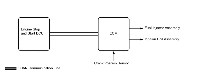
Early Stage Injection Control
-
Early stage injection control shortens the time it takes the engine to restart after the stop and start system stops the engine, thus allowing smooth initial acceleration.
-
The ECM memorizes the crankshaft angle detected by the crank position sensor when the engine is stopped by the stop and start system.
-
The ECM judges the injection required and decides which cylinder to ignite when the driver does restart operation. The ECM then uses this information as it starts the engine.
-
-
Hill-start Assist Function
-
The driving force (creep phenomenon) of a former AT vehicle is regulated by depressing the brake pedal while stopped, and the driving force is transmitted by releasing the brake pedal when starting the vehicle. However, when starting a stop and start system equipped vehicle with its engine stopped due to the activation of the idle stop function, there is a short time delay before the driving force is generated as the engine will start after the brake pedal is released.
-
The hill-start assist function is a system to assist starting of a stop and start system equipped vehicle on a slope to deal with the situation described above, retaining the brake hydraulic pressure until sufficient driving force is generated.
-
-
System Prohibit Control
-
For safety, battery protection, comfort and ECU learning reasons, the engine stop and start ECU prohibits stop and start system operation if any one of the following conditions is met.
Prohibition Reason Condition Safety If the engine is started with the hood open, such as when jump starting, engine restart operation cannot be ensured. Therefore, stop and start system operation will be prohibited. Operation of the system will be restored on the next trip. If the driver door or hood is opened before the engine stops, stop and start system operation will be prohibited for safety reasons. The brake booster vacuum is insufficient. The driver seat belt is unfastened before the engine stops. The engine catalyst is being quickly warmed up. Battery Protection While recharging, stop and start system operation will be disabled. The recharging continues for 0.5 to 1 hour, and is carried out approximately every about 30 hours or driving. If the idle stop rate becomes higher than a predetermined value, stop and start system operation will be disabled. If the battery voltage becomes low and the battery integrated current value drops to below the threshold value, stop and start operation will be disabled. Comfort If the air conditioning is on when the outside temperature is high and the evaporator temperature is high, stop and start system operation will be prohibited. If the air conditioning is on when the outside temperature is low, stop and start system operation will be prohibited. If the heater is on when the outside temperature is low and the engine coolant temperature is low, stop and start system operation will be prohibited. If the front DEF switch and blower switch are on, stop and start system operation will be prohibited. ECM Learning ECM learning is not complete.* Operability If the vehicle is stopped while the steering wheel is being operated, stop and start system operation will be prohibited. Tech Tips
*: If the value learned by the ECU has been cleared by disconnecting the battery or for another reason, stop and start system operation will be prohibited until ECU learning is complete.
-
-
Warning Control
-
If any of the following operations are performed while the engine is stopped due to system control, the system will not restart the engine. The driver will be warned by a buzzer, or the engine will be regarded as stalled or will be restarted.
Operation Warning Control Hood is opened. The engine status changes to 'stalled' or is restarted. Driver seat belt is unfastened. The engine is restarted.
-
-
Electric Oil Pump for AT Control
-
Because the engine stop and start ECU operates the electric oil pump for AT during idle stop, a stable AT oil pressure is ensured, enabling a smooth vehicle start.
-
Engine stop and start ECU actuates the electric oil pump for AT when it receives an engine stop signal and the following condition is met. The electric oil pump for AT will stop operating when the engine automatically starts and the engine speed exceeds a specified value.
Electric Oil Pump for AT Operation Shift Position P R N D S Brake On (applied) - - - ○ - Brake Off (not applied) - - - - -
-
○: Operating
-
-: Idle stop is disabled
Electric Oil Pump for AT Operating Condition Item Condition Remarks AT Oil Temperature 25 to 112°C (77 to 233.6°F) Detected from the oil temperature sensor in the AT -
-
-
-
CONSTRUCTION
-
Backup Boost Converter
-
The backup boost converter is built into the engine stop and start ECU.
-
The backup boost converter uses a semiconductor relay. The semiconductor relay also functions as a fuse. When overcurrent is detected, the relay is turned off to protect the circuit.
-
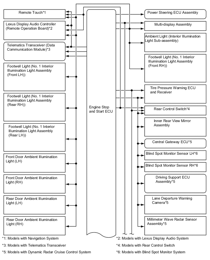
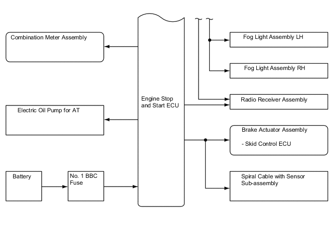
The backup boost converter supplies battery voltage to help make up for the voltage drop that occurs when the engine is restarted. This prevents the operation of the following equipment from being interrupted due to low battery voltage.
-
Remote Touch*1
-
Lexus Display Audio Controller (Remote Operation Board)*2
-
Telematics Transceiver (Data Communication Module)*3
-
Footwell Light (No. 1 Interior Illumination Light Assembly (Front LH))
-
Footwell Light (No. 1 Interior Illumination Light Assembly (Rear RH))
-
Footwell Light (No. 1 Interior Illumination Light Assembly (Rear LH))
-
Front Door Ambient Illumination Light (LH)
-
Front Door Ambient Illumination Light (RH)
-
Rear Door Ambient Illumination Light (LH)
-
Rear Door Ambient Illumination Light (RH)
-
Power Steering ECU Assembly
-
Multi-display Assembly
-
Ambient Light (Interior Illumination Light Sub-assembly)
-
Footwell Light (No. 1 Interior Illumination Light Assembly (Front RH))
-
Tire Pressure Warning ECU and Receiver
-
Rear Control Switch*4
-
Inner Rear View Mirror Assembly
-
Central Gateway ECU*5
-
Blind Spot Monitor Sensor LH*6
-
Blind Spot Monitor Sensor RH*6
-
Driving Support ECU Assembly*5
-
Lane Departure Warning Camera*5
-
Millimeter Wave Radar Sensor Assembly*5
-
Fog Light Assembly LH
-
Fog Light Assembly RH
-
Radio Receiver Assembly
-
Skid Control ECU
-
Spiral Cable with Sensor Sub-assembly
Tech Tips
*1: Models with navigation system
*2: Models with lexus display audio system
*3: Models with telematics transceiver
*4: Models with rear control switch
*5: Models with dynamic radar cruise control system
*6: Models with blind spot monitor system
-
-
An external backup boost converter (eco run vehicle converter assembly) is used.
-
When the audio system is used during idle stop, the external backup boost converter (eco run vehicle converter assembly) compensates for the voltage drop to supplement audio playback by stabilizing the sound quality.
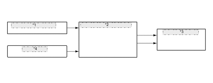
External Backup Boost Converter (Eco Run Vehicle Converter Assembly) *1 Engine Stop and Start ECU *2 External Backup Boost Converter (Eco Run Vehicle Converter Assembly) *3 Stereo Component Amplifier Assembly *4 No. 2 BBC Fuse
-
-
Electric Oil Pump for AT
-
The electric oil pump for AT is provided for the stop and start system and is controlled by the engine stop and start ECU.
-
The electric oil pump for AT enables a stable Automatic Transmission Fluid (ATF) supply during idle stop, and delivers good responsiveness and smoothness at the time of start off.
-
The electric oil pump for AT only operates when the engine is in the idle stop status. While the engine is operating, ATF is supplied from the oil pump assembly.
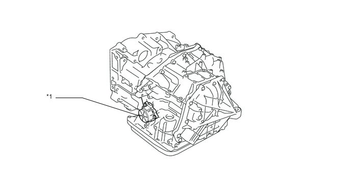
Text in Illustration *1 Electric Oil Pump for AT - - -
The electric oil pump for AT consists of an oil pump motor driver section, DC sensorless and brushless motor section, and oil pump section.
-
The oil pump motor driver controls the electric oil pump for AT according to the signals from the engine stop and start ECU.
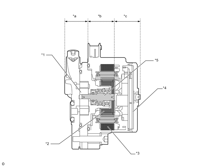
Text in Illustration *1 Pump Rotor *2 Magnet *3 Stator Core *4 Oil Pump Motor Driver *5 Shaft - - *a Oil Pump Section *b DC Sensorless and Brushless Motor Section *c Oil Pump Motor Driver Section - - -
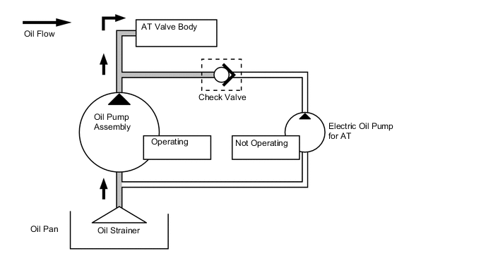
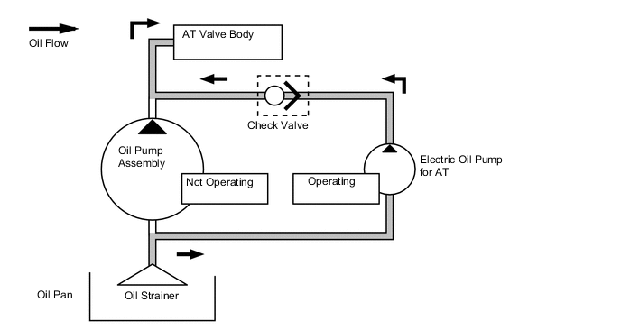
The oil pump assembly generates oil pressure using the engine power. At this time, the fluid pressure generated by the electric oil pump for AT is cut off by the check valve provided at the electric oil pump for AT discharge part and the electric oil pump for AT does not operate.
-
During idle stop, the regular oil pump assembly operation stops. At this time, the electric oil pump for AT operates to generate fluid pressure, open the check valve and supply ATF to the AT valve body.
-
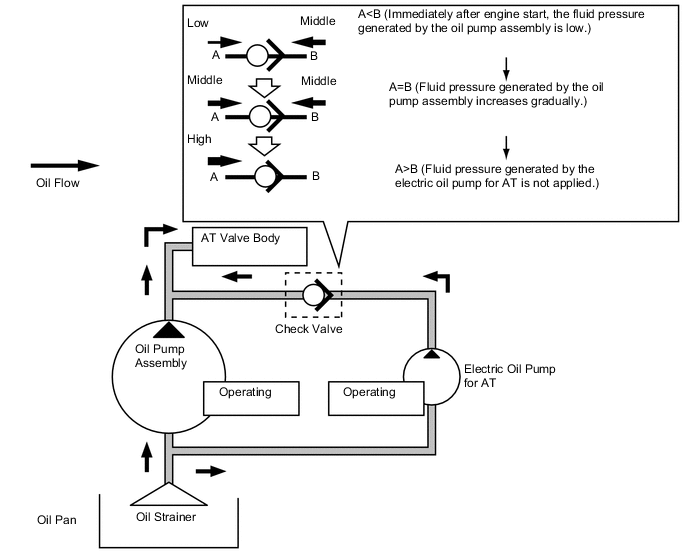
When the engine restarts, both the fluid pressure generated by the electric oil pump for AT and the fluid pressure generated by the oil pump assembly are applied to the AT valve body. At this time, if the fluid pressure generated by the oil pump assembly becomes higher than the fluid pressure generated by the electric oil pump for AT, the check valve will close and the fluid pressure generated by the electric oil pump for AT will not be applied. Operation of the electric oil pump for AT is stopped according to the engine speed and other signals.
-
-
-
OPERATION
-
Combination Meter Assembly
-
The combination meter assembly receives the idling on/off signals from the engine stop and start ECU.
-
By changing the display mode of the multi-information display by operating the multi-information switch on the steering pad switch assembly, the amount of time idling stop was performed since the engine switch was turned to on (IG) to when the engine switch was turned off or the amount of time idling stop was performed since the reset switch was last pressed can be displayed.
-
The system operation status or warning information is indicated to the driver through the following means:
-
Illuminating or flashing the stop and start indicator light and stop and start cancel indicator light on the multi-information display in the combination meter assembly.
-
Sounding a buzzer.
-
Displaying other information on the multi-information display.
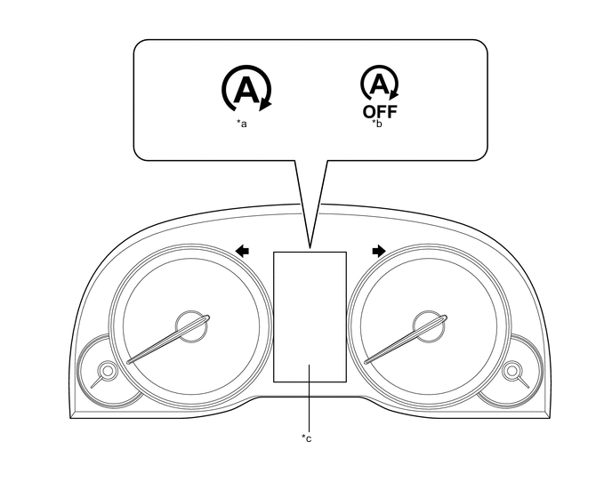
Text in Illustration *a Stop and Start Indicator Light *b Stop and Start Cancel Indicator Light *c Multi-information Display - - Stop and Start Indicator Light Operation Item Condition Stop and Start Indicator Light Buzzer System Operating (Engine is stopped) The vehicle is operating normally. Illuminates Does not sound The driver's door is opened with the shift lever in D. Blinks* Sounds Tech Tips
*: The blinking interval is 0.5 seconds.
Stop and Start Cancel Indicator Light Operation Condition Stop and Start Cancel Indicator Light The vehicle is stopped and system operation conditions are met. OFF When the stop and start cancel switch is ON. Illuminates When any Diagnostic Trouble Code (DTCs) are detected. Blinks* When the number of times the starter assembly has been operated exceeds Blinks* the threshold. Tech Tips
*: The blinking interval is 0.5 seconds.
Multi-information Display Operation Display Operation Condition Multi-information Display System Malfunction Display A system malfunction is detected. Stop & Start System Malfunction Visit Your Dealer Display of Temporary Cancellation of Idling Stop Operation The driver's seatbelt is unfastened during idling stop. Driver seat belt unbuckled The driver operates the steering wheel more than a specified angle during idling stop. Steering wheel turned Hydraulic pressure of brakes becomes insufficient during idling stop. For brake system Cooling performance of the air conditioning system deteriorates during idling stop. For climate control Battery charge amount decreases during idling stop. Battery charging Display of Prohibition Status of Stop and Start Control Battery charge amount decreases and becomes insufficient for the engine stop requirements. Battery charging Hydraulic pressure of brakes is insufficient. For brake system The driver's seatbelt is unfastened. Driver seat belt unbuckled When a battery that is not specified is used and the battery voltage is below the lowest engine starting voltage. Non-Dedicated Battery Display of Standby State of Stop and Start Control Brake pedal depression is insufficient for the engine stop requirement. Depress brake firmly to activate. -
-
-
-
DIAGNOSIS
-
When the engine stop and start ECU detects a malfunction and CAN communication is normal, the engine stop and start ECU records information related to the malfunction. Furthermore, the stop and start indicator light in the combination meter assembly blinks to inform the driver that CAN communication is normal.
-
The engine stop and start ECU also stores Diagnostic Trouble Codes (DTCs) related to malfunctions. DTCs can be read using the Global TechStream (GTS).
-