FUEL SYSTEM
-
FUNCTION OF MAIN COMPONENTS
-
The D-4S system has the following components and functions:
Component Function Fuel Pump Assembly (for Low Pressure) Sends fuel (420 kPa) from the fuel tank assembly to the fuel pump assembly (for high pressure) and fuel injector assembly (for port injection). Fuel Pump Assembly (for High Pressure) Increases the pressure of the fuel from the fuel pump assembly (for low pressure) to a pressure of 4.0 to 20 MPa and sends it to the fuel delivery pipe sub-assembly (for direct injection). Spill Control Valve (built-in Fuel Pump Assembly (for High Pressure)) Closes and opens the fuel flow path to the high-pressure fuel system in accordance with signals from the ECM. Fuel Pressure Pulsation Damper Assembly (built-in Fuel Pump Assembly (for High Pressure)) Reduces fuel pressure fluctuation (pulsation) and noise. Fuel Delivery Pipe Sub-assembly (for Port Injection) Delivers the low-pressure fuel to the fuel injector assembly (for port injection). Fuel Delivery Pipe Sub-assembly (for Direct Injection) Delivers the high-pressure fuel to the fuel injector assembly (for direct injection). Fuel Pressure Sensor Senses the fuel pressure and outputs a signal to the ECM. Fuel Injector Assembly (for Port Injection) Injects a calculated (by the ECM) quantity of 420 kPa (low pressure) fuel into the intake port. Fuel Injector Assembly (for Direct Injection) Injects a calculated (by the ECM) quantity of 4.0 to 20 MPa (high pressure) fuel directly into the combustion chamber. ECM Depending on the vehicle condition, and based on signals from various sensors, the ECM calculates the optimal injection timing and volume, and controls the fuel injector assembly (for direct injection) and fuel pump assembly (for high pressure).
-
-
FUNCTION
-
D-4S System
-
The Direct injection 4-stroke gasoline engine Superior version (D-4S) system has both direct type fuel injection, which directly injects high-pressure fuel into the combustion chamber, and port type fuel injection, which injects fuel into the intake port. The system optimally controls the fuel injectors for direct injection and port injection according to engine load.
-
In low to medium engine load ranges, both direct type and port type fuel injections are used together or one of them is used to create homogeneous mixed air, thus contributing to stable combustions. With this, the system achieves low fuel consumption and low emissions. In addition, in high engine load ranges, only the direct type fuel injection is used to cool down the intake air with the chilling effect of vapors in the fuel which is injected into the cylinder, improving charging efficiency and anti-knock properties.
-
Immediately after the engine is started in cold state, the fuel injector assembly on the port side is selected for the injection aiming at homogenizing the mixture in the combustion chamber. Next, the fuel injector assembly on the cylinder injection side performs fuel injection during the compression process in order to stratify the mixture layers around the spark plug. This formation not only enables a substantial retardation of ignition timing but also raises the in exhaust gas temperature, which facilitates the warm-up of the catalyst following a cold start.
-
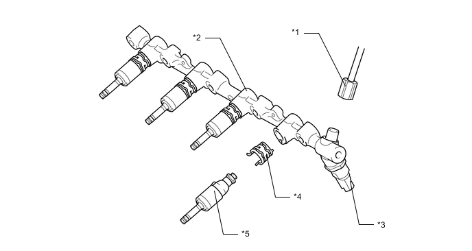
A high-pressure single slit-nozzle injector is used as the fuel injector assembly (for direct injection). The fuel atomized by this injector is injected into the combustion chamber via the slit, spreading in a fan shaped pattern and combines with a large volume of intake air. The intake air will swirl in a vertical direction and promote mixture with the fuel, contributing to higher performance and higher output.
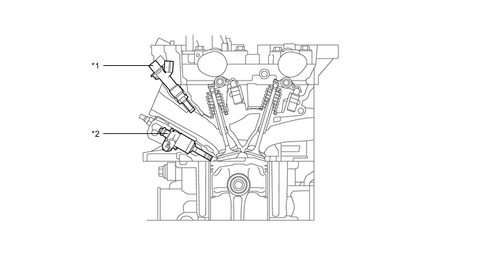
Text in Illustration *1 Fuel Injector Assembly (for Port Injection) *2 Fuel Injector Assembly (for Direct Injection)
-
-
Fuel Returnless Control
-
A fuel returnless system is used to reduce evaporative emissions. As shown below, by integrating the fuel filter assembly, fuel pressure regulator assembly and fuel pump assembly (for low pressure), it is possible to discontinue the return of fuel from the engine area, thus preventing temperature rise inside the fuel tank assembly. This reduces the generation of evaporative emissions in the fuel tank assembly.
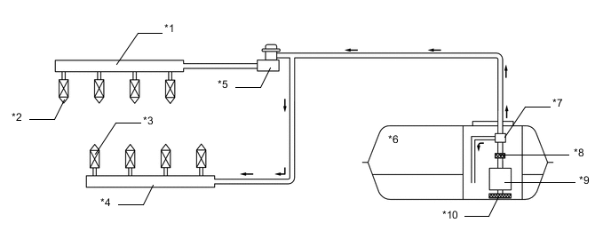
Text in Illustration *1 Fuel Delivery Pipe Sub-assembly (for Direct Injection) *2 Fuel Injector Assembly (for Direct Injection) *3 Fuel Injector Assembly (for Port Injection) *4 Fuel Delivery Pipe Sub-assembly (for Port Injection) *5 Fuel Pump Assembly (for High Pressure) *6 Fuel Tank Assembly *7 Fuel Pressure Regulator Assembly *8 Fuel Filter Assembly *9 Fuel Pump Assembly (for Low Pressure) *10 Fuel Suction Filter
-
-
-
CONSTRUCTION
-
Fuel Tank Assembly
-
A fuel tank assembly made of sheet steel is used.
-
Low fuel vapor permeability is achieved by the use of sheet steel.
-
-
Fuel Pump Assembly (for Low Pressure)
-
A compact fuel pump assembly (for low pressure) is used. Its basic components are a fuel pump, a fuel filter assembly, a charchoal canister, a pressure regulator assembly and a fuel sender gauge assembly.
-
The fuel pump assembly (for low pressure) is located in the fuel tank assembly. This fuel pump pressurizes the fuel from the fuel tank assembly and sends the fuel to the high-pressure and low-pressure fuel systems.
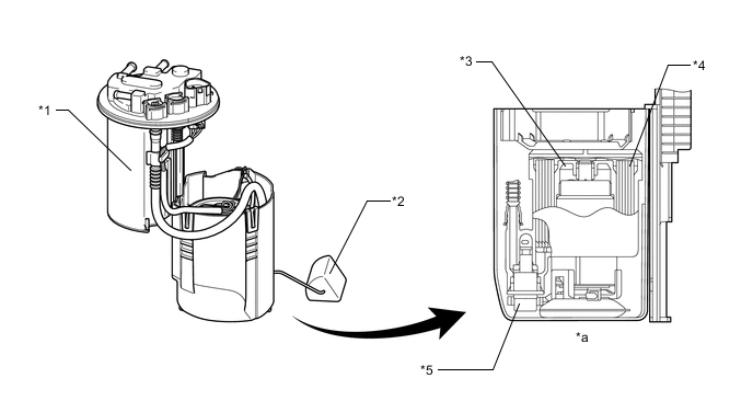
Text in Illustration *1 Charcoal Canister *2 Fuel Sender Gauge *3 Fuel Pump *4 Fuel Filter *5 Fuel Pressure Regulator Assembly - - *a Cross Section - -
-
-
Fuel Pump Assembly (for High Pressure)
-
The fuel pump assembly (for high pressure) is composed of an electromagnetic spill valve that adjusts the discharge amount of high pressurized fuel, a plunger that is driven by the intake camshaft to pressurize fuel, a check valve that mechanically opens and closes the path to the fuel delivery pipe sub-assembly (for direct injection) and a fuel relief valve that releases the fuel when a malfunction is detected in the high-pressure fuel system. In addition, to reduce fuel pulsations, a fuel pressure pulsation damper assembly is installed at the inlet for low pressure fuel flowing from the fuel tank assembly.
-
A roller lifter (fuel pump lifter assembly) is provided to cope with higher output performance and higher pressurized fuel.
-
The plunger is moved up and down by a lobe that is located at the rear end of the intake camshaft of the engine. This lobe causes 4 strokes of the pump piston to occur for each camshaft revolution (4 protrusions exist 90 degrees from each other on the same camshaft "lobe").
-
The pressure of highly pressurized fuel is adjusted between 4.0 to 20 MPa in accordance with the vehicle driving conditions, reducing friction loss.
-
A spill control valve is used to control the pump discharge pressure. The spill control valve is located in the inlet passage of the fuel pump assembly (for high pressure). The valve is electrically opened and closed by the ECM.
-
A check valve is present in the outlet of the fuel pump assembly (for high pressure). As the pressure in the outlet of the pump rises and becomes high enough to push the check valve off its seat, fuel will begin to flow to the fuel delivery pipe sub-assembly (for direct injection) (minimum pressure to open the check valve is 60 kPa).

Text in Illustration *1 Spill Control Valve *2 Roller Lifter (Fuel Pump Lifter Assembly) *3 Fuel Injector Assembly (for Direct Injection) *4 Fuel Delivery Pipe Sub-assembly (for Direct Injection) *5 Fuel Pressure Sensor *6 Fuel Tank Assembly *7 Fuel Pressure Regulator Assembly *8 Fuel Filter Assembly *9 Fuel Pump Assembly (for Low Pressure) *10 Fuel Suction Filter *11 Fuel Pressure Pulsation Damper Assembly *12 Plunger *13 Check Valve (60 kPa) *14 Fuel Relief Valve (23.6 MPa) *15 Fuel Pump Assembly (for High Pressure) *16 Intake Camshaft (Cam to Drive Fuel Pump) *a Low-pressure Fuel (from Fuel Pump Assembly (for Low Pressure)) *b High-pressure Fuel (to Fuel Delivery Pipe Sub-assembly (for Direct Injection)) *c to Fuel Delivery Pipe Sub-assembly (for Port Injection) *d High-pressure Fuel Pipe
-
-
Fuel Delivery Pipe Sub-assembly (for Port Injection)
-
A pressed steel fuel delivery pipe sub-assembly (for port injection) is used.
-
A pressed fuel delivery pipe sub-assembly (for port injection), whose walls create a damping effect on fuel pressure vibrations (pulses) that occur when the fuel injector assembly (for port injection) injects fuel, is used. As a result, the fuel pressure pulsation damper was able to be discontinued, reducing the number of parts while achieving weight and size reduction.
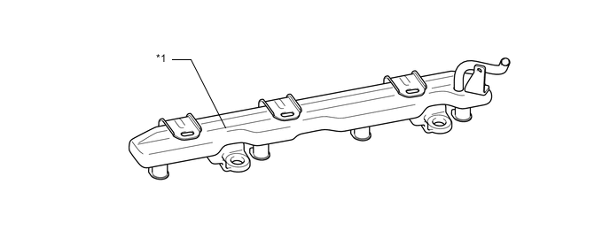
Text in Illustration *1 Fuel Delivery Pipe Sub-assembly (for Port Injection) - -
-
-
Fuel Delivery Pipe Sub-assembly (for Direct Injection)
-
Cast-iron is used for the fuel delivery pipe sub-assembly (for direct injection).
-
A fuel pressure sensor is installed on the fuel delivery pipe sub-assembly (for direct injection).
-
A nozzle holder clamp is provided for each area where a fuel injector assembly is installed. This clamp applies a constant spring force to the fuel injector assembly to prevent it from moving when the combustion pressure is applied to the injector while the engine is being started, during which the fuel pressure is low. As a result, the clamp increases the sealing performance of the injector, while reducing vibration and noise.
-
Metal-to-metal surface seal connections are used for the joint areas of the fuel pressure sensor and high-pressure fuel pipes.
Text in Illustration *1 High-pressure Fuel Pipe *2 Fuel Delivery Pipe Sub-assembly (for Direct Injection) *3 Fuel Pressure Sensor *4 Nozzle Holder Clamp *5 Fuel Injector Assembly (for Direct Injection) - -
-
-
Fuel Injector Sub-assembly (for Port Injection)
-
A high-atomization 12-hole long nozzle fuel injector assembly is used. Through the adoption of a long nozzle type injector, airflow in the intake port is optimized and the amount of fuel adhesion is reduced, contributing to higher fuel efficiency and reduced emissions.
-
Moving parts and magnetic circuits have been optimized to realize an expanded dynamic range of the fuel injection volume and excellent high temperature characteristics, contributing to higher fuel efficiency and reduced emissions.
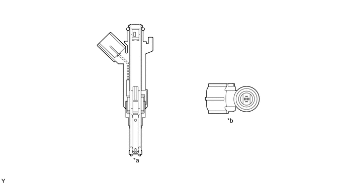
Text in Illustration *a Fuel Injector Assembly (for Port Injection) Cross Section *b Injector Nozzle
-
-
Fuel Injector Sub-assembly (for Direct Injection)
-
High-pressure, single slit-nozzle type fuel injector assemblies are used in conjunction with the adoption of the Direct injection 4-stroke gasoline engine Superior version (D-4S) system.
-
The use of this fuel injector assembly (for direct injection) causes the fuel to become highly atomized and spread over a wide fan-shaped area. At the same time, the fuel is mixed with a large amount of air and injected into the combustion chamber. As a result, fuel injection dissipation performance is improved to achieve a homogeneous air-fuel mixture, high performance and high engine output.
-
A Teflon sealant is used for the cylinder internal pressure sealant and an insulator is used at the cylinder head sub-assembly contact area to reduce vibration and noise and improve sealing performance.
-
An O-ring and backup ring* are used in the fuel injector assembly (for direct injection). As a result, the transmission of operation noise from the fuel injector assembly (for direct injection) is reduced to improve quietness and ensure fastener airtightness.
Note
*: The backup ring is installed to securely support the rubber O-ring, which is subjected to high pressures. Take care to install the backup ring in the correct direction at the correct installation position.
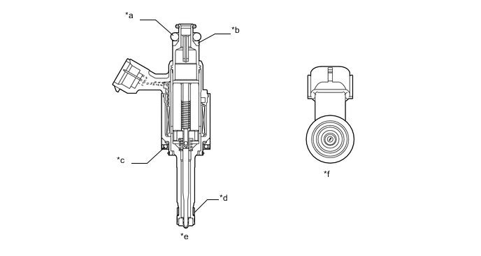
Text in Illustration *a O-ring *b Backup Ring *c Insulator *d Teflon Sealant *e Fuel Injector Assembly (for Direct Injection) Cross Section *f Injection Hole
-
-
-
OPERATION
-
Fuel Pump Assembly (for High Pressure)
-
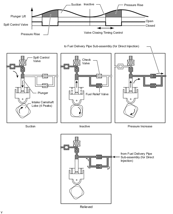
During the intake portion of the pump cycle, the spill control valve is opened, and the pump plunger (piston) is moved downward by spring force. This allows fuel to be drawn into the cylinder of the pump. If the spill control valve has not been closed yet, when the cam forces the plunger to move upward, the fuel in the pump cylinder (this fuel is not pressurized) will be pushed back to the pump inlet (fuel tank side).
-
In order to close the spill control valve as the piston is moving upward, the ECM sends a signal to the valve. When the spill control valve is closed and the plunger is moving upward, the pressure in the pump cylinder will rise. As this pressure rises above 60 kPa (or the pressure of the delivery pipe, whichever is higher), the fuel will begin to flow to the fuel delivery pipe sub-assembly (for direct injection). The ECM calculates the target fuel pressure based on driving conditions. The ECM controls the pressure by operating the spill control valve. The timing and duration of the spill control valve closing are varied to cause the pump pressure to meet the target pressure.
-
If the fuel pressure in the high-pressure fuel pipes is abnormally high, the relief valve discharges some of fuel in order to limit the pressure.
-
-