ENGINE UNIT
-
CONSTRUCTION
-
Cylinder Head Cover Sub-assembly
-
A lightweight and high-strength magnesium cylinder head cover sub-assembly is used.
-
An oil delivery pipe is installed inside each cylinder head cover sub-assembly. This ensures lubrication to the sliding parts of the No. 1 valve rocker arm sub-assemblies, improving reliability.
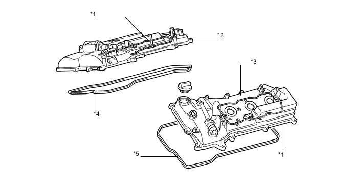
Text in Illustration *1 Oil Delivery Pipe *2 Cylinder Head Cover Sub-assembly *3 Cylinder Head Cover Sub-assembly LH *4 Cylinder Head Cover Gasket *5 Cylinder Head Cover Gasket No. 2 - -
-
-
Cylinder Head Gasket and No. 2 Cylinder Head Gasket
-
Steel-laminate type cylinder head gaskets are used. A shim is used around the cylinder bore of each gasket to help enhance sealing performance and durability.
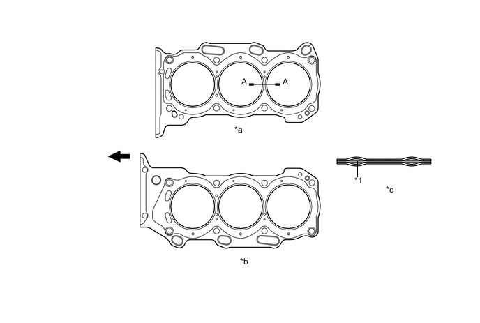
Text in Illustration *1 Shim - - *a for Bank 1 *b for Bank 2 *c A-A Cross Section - - 
Engine Front - -
-
-
Cylinder Head Sub-assembly and Cylinder Head LH
-
The cylinder head structure is simplified by separating the cam journal portion (camshaft housing sub-assembly) from the cylinder head.
-
The cylinder head, which is made of aluminum, contains pentroof-type combustion chambers. The spark plug is located in the center of the combustion chamber in order to improve the engine's anti-knock performance.
-
The intake ports are on the inside and the exhaust ports on the outside of the left and right banks respectively.
-
A taper squish combustion chamber is used to improve anti-knock performance and intake efficiency. In addition, engine performance and fuel economy are improved.
-
Siamese type intake ports are used to reduce the overall surface area of the intake port walls. This prevents some fuel from adhering to the intake port walls, thus reducing HC exhaust emissions.
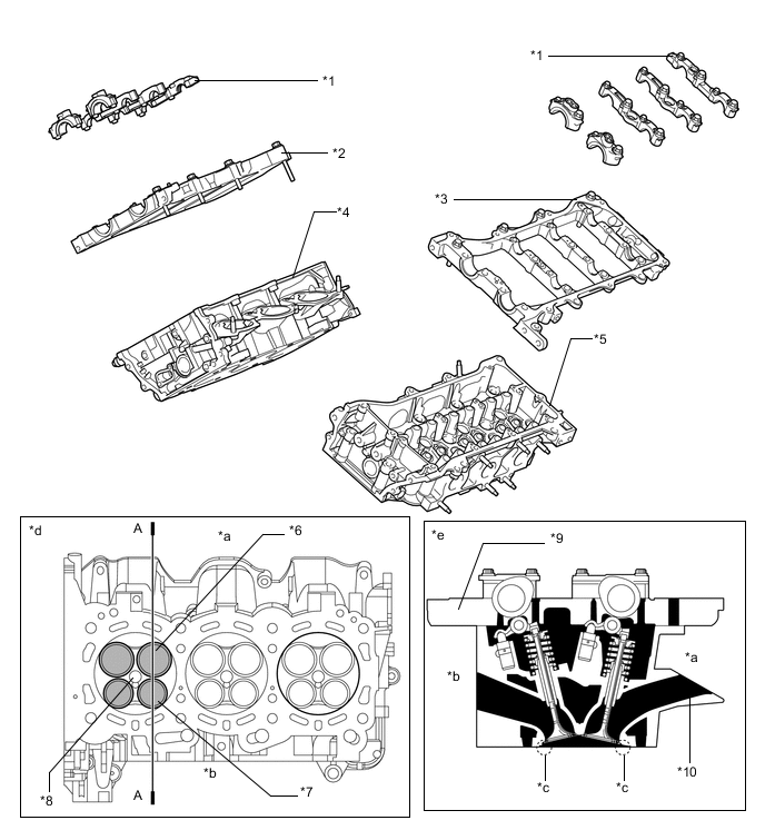
Text in Illustration *1 Camshaft Bearing Cap *2 Camshaft Housing Sub-assembly RH *3 Camshaft Housing Sub-assembly LH *4 Cylinder Head Sub-assembly *5 Cylinder Head LH *6 Intake Valve *7 Exhaust Valve *8 Spark Plug Hole *9 Camshaft Housing *10 Upright Intake Port *a Intake Side *b Exhaust Side *c Taper Squish Area *d View from Bottom *e A-A Cross Section - - Tech Tips
The difference between a siamese type intake port and independent type one is shown in the illustration.
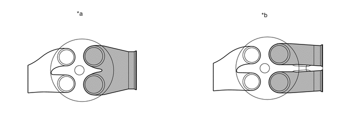
Text in Illustration *a Siamese Type *b Independent Type
-
-
Cylinder Block Sub-assembly
-
The cylinder block sub-assembly is made of aluminum alloy, so it is lightweight.
-
The cylinder block sub-assembly has a bank angle of 60°, a bank offset of 36.6 mm (1.441 in.) and a bore pitch of 105 mm (4.15 in.), resulting in a compact block (length and width) for its displacement.
-
Installation bosses for the 2 knock control sensors are located on the inside of the left and right banks.
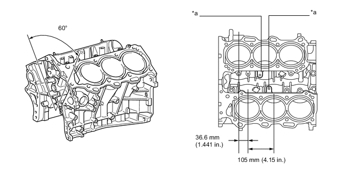
Text in Illustration *a Knock Control Sensor Boss - - -
Water passages are provided between the cylinder bores. By allowing the engine coolant to flow between the cylinder bores, this construction enables the temperature of the cylinder walls to be kept uniform.
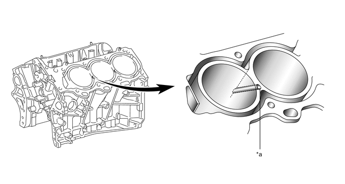
Text in Illustration *a Water Passage - - -
A compact block has been achieved by producing the thin cast-iron liners and cylinder block sub-assembly as a unit. It is not possible to rebore a block which uses this type of liner.
-
The liners are a spiny-type, which have been manufactured so that their casting exterior forms large irregular surfaces in order to enhance the adhesion between the liners and the aluminum cylinder block sub-assembly. The enhanced adhesion helps improve heat dissipation, resulting in a lower overall temperature and reduced heat deformation of the cylinder bores.
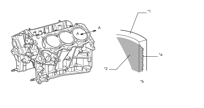
Text in Illustration *1 Cylinder Block *2 Liner *a Irregularly shaped outer casting surface of liner *b A-A Cross Section
-
-
Piston
-
The pistons are made of aluminum alloy.
-
The tops of the pistons utilize a taper squish shape to achieve fuel combustion efficiency.
-
The piston skirts are coated with resin to reduce friction losses.
-
The groove of the top ring is coated with alumite to ensure abrasion resistance.
-
By increasing the machining precision of the cylinder bore diameter in the block, only one size piston is required.
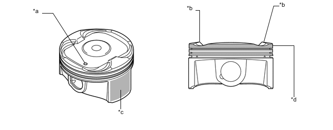
Text in Illustration *a Front Mark *b Taper Squish Shape *c Resin Coating *d Alumite Coating
-
-
Connecting Rod Sub-assembly
-
Connecting rod sub-assemblies that have been forged for high strength are used for weight reduction.
-
Knock pins are used at the mating surfaces of the connecting rod caps to minimize the shifting of the connecting rod caps during assembly.
-
Nutless-type plastic region tightening bolts are used on the connecting rod sub-assemblies for a lighter design.
-
Aluminum bearings are used for the connecting rod bearings.
-
The connecting rod bearings are reduced in width to reduce friction.
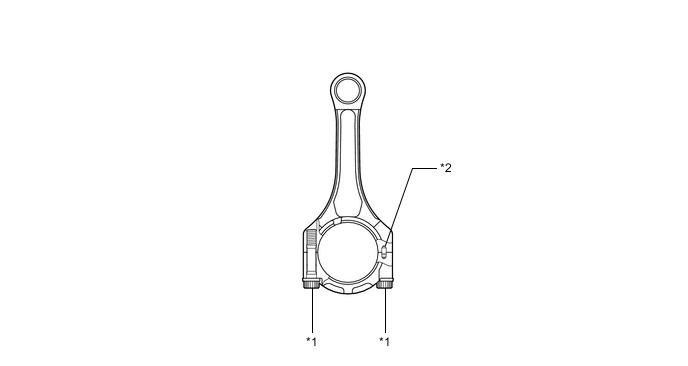
Text in Illustration *1 Plastic Region Tightening Bolt *2 Knock Pin
-
-
Crankshaft
-
A crankshaft made of forged steel, which excels in rigidity and wear resistance, is used.
-
The crankshaft has 4 main bearing journals and 5 balance weights.
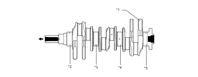
Text in Illustration *1 Balance Weight *2 No. 1 Journal *3 No. 2 Journal *4 No. 3 Journal *5 No. 4 Journal - - Engine Front - -
-
-
Crankshaft Bearing and Crankshaft Bearing Cap
-
The crankshaft main bearings are made of aluminum alloy.
-
Similar to the connecting rod bearings, the lining surface of the crankshaft bearings is micro-grooved to realize an optimal amount of oil clearance. As a result, cold-engine cranking performance is improved and engine vibration is reduced.
-
The upper crankshaft bearings have an oil groove around the inside circumference.
-
The crankshaft bearing caps are tightened using 4 plastic region tightening bolts for each journal. In addition, each cap is tightened laterally to improve its reliability.
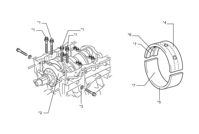
Text in Illustration *1 Plastic Region Tightening Bolt *2 Crankshaft Bearing Cap *3 Seal Washer *4 Upper Crankshaft Bearing *5 Lower Crankshaft Bearing *6 Oil Groove *7 Micro-grooved surface - -
-
-
Crankshaft Pulley
-
The rigidity of the crankshaft pulley with its built-in torsional damper rubber reduces noise.

Text in Illustration *1 Torsional Damper Rubber - -
-
-
Oil Pan
-
The oil pan sub-assembly is made of aluminum alloy.
-
The No. 2 oil pan sub-assembly is made of steel.
-
The oil pan sub-assembly is secured to the cylinder block sub-assembly and the transaxle housing to increase rigidity.
-
The oil filter case is integrated with the oil pan sub-assembly.
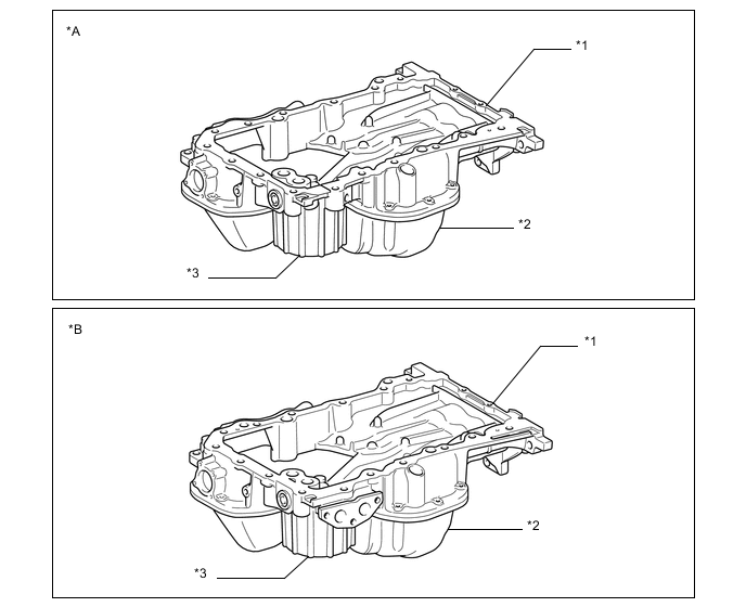
Text in Illustration *A Except Models for G.C.C. Countries *B Models for G.C.C. Countries *1 Oil Pan Sub-assembly *2 No. 2 Oil Pan Sub-assembly *3 Oil Filter Case - -
-
-
Valve Mechanism
-
Each cylinder of this engine has 2 intake valves and 2 exhaust valves. Intake and exhaust efficiency is increased due to larger total port areas.
-
This engine uses roller rocker arms with built-in needle bearings. This reduces the friction that occurs between the cams and the roller rocker arms when the valves are pushed down, thus improving fuel economy.
-
Valve lash adjuster assemblies, which maintain a constant zero valve clearance through the use of oil pressure and spring force, are used.
-
The intake camshafts are driven by the crankshaft via the primary timing chain. The exhaust camshafts are each driven by the intake camshaft of their respective bank via a secondary chain.
-
This engine has the Dual Variable Valve Timing-intelligent (Dual VVT-i) system which controls the intake camshafts and exhaust camshafts to provide optimal valve timing according to driving conditions. With this adoption, lower fuel consumption, higher engine performance, and fewer exhaust emissions have been achieved. For details, refer to the Dual VVT-i control.
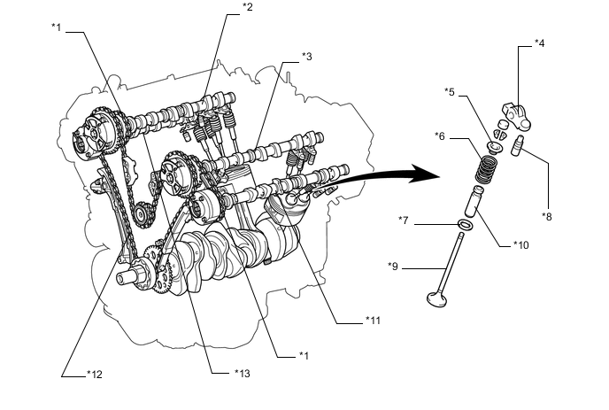
Text in Illustration *1 No. 2 Chain Sub-assembly (Secondary) *2 Camshaft (RH, Intake) *3 No. 3 Camshaft Sub-assembly (LH, Intake) *4 No. 1 Valve Rocker Arm Sub-assembly *5 Valve Spring Retainer *6 Compression Spring *7 Valve Spring Seat *8 Valve Lash Adjuster Assembly *9 Valve *10 Valve Guide Bush *11 No. 4 Camshaft Sub-assembly (LH, Exhaust) *12 Chain Sub-assembly (Primary) *13 No. 2 Camshaft (RH, Exhaust) - -
-
-
Valve Timing
Intake Valve Open -3° to 37° BTDC Close 71° to 31° ABDC Exhaust Valve Open 60° to 25° BBDC Close 4° to 39° ATDC 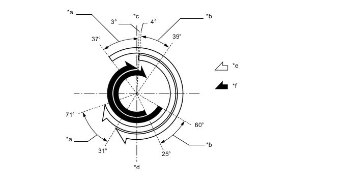
Text in Illustration *a Intake VVT-i Operation Range *b Exhaust VVT-i Operation Range *c TDC *d BDC *e Intake Valve Operation Angle *f Exhaust Valve Operation Angle -
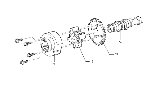
Camshaft
-
The camshafts are made of cast iron alloy.
-
Oil passages are provided on the intake and exhaust camshafts in order to supply engine oil to the VVT-i system.
-
Camshaft timing gear assemblies (LH and RH) and camshaft timing exhaust gear assemblies (LH and RH) are installed on the front of the camshafts to vary the timing of the intake and exhaust valves.
-
Together with the use of the roller rocker arms, the cam profile has been modified. This results in increased valve lift when the valve begins to open and as it finishes closing, helping to achieve enhanced output performance.
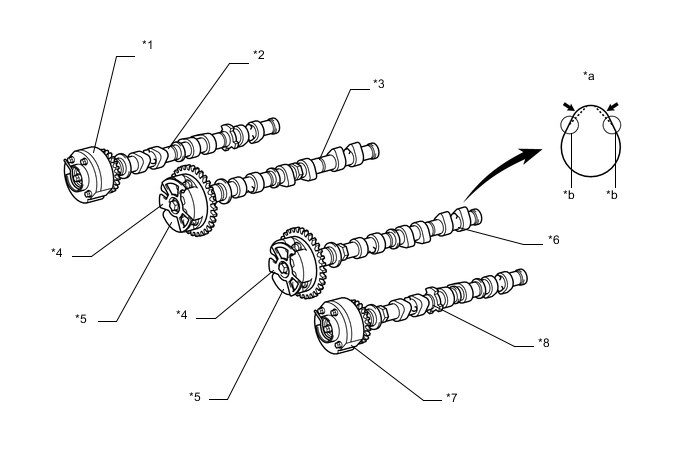
Text in Illustration *1 Camshaft Timing Exhaust Gear Assembly RH *2 No. 2 Camshaft *3 Camshaft *4 Timing Rotor *5 Camshaft Timing Gear Assembly *6 No. 3 Camshaft Sub-assembly *7 Camshaft Timing Exhaust Gear Assembly LH *8 No. 4 Camshaft Sub-assembly *a Increased Valve Lift *b Modified Portion of Cam Profile
-
-
Camshaft Timing Gear Assembly (Intake)
-
The camshaft timing gear assemblies each consist of an outer housing that is driven by the timing chain sprocket, and a vane sub-assembly that is coupled to each camshaft.
-
The camshaft timing gear assembly uses a vane sub-assembly with 3 lobes.
-
When the engine stops, each camshaft timing gear assembly is locked at the most retarded angle by its lock pin. This ensures excellent engine startability.
-
The oil pressure sent from the advance or retard side passages of the intake camshafts causes rotation of the vane sub-assembly relative to the timing chain sprocket, varying the valve timing continuously.
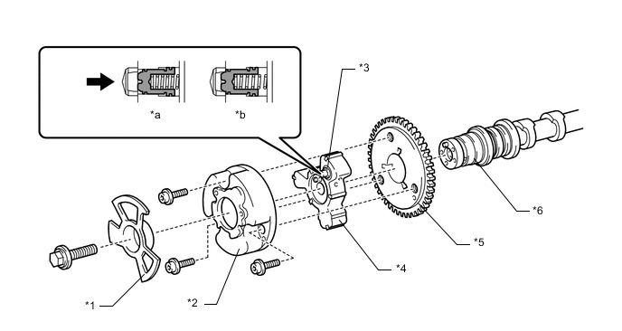
Text in Illustration *1 Timing Rotor *2 Outer Housing *3 Lock Pin *4 Vane Sub-assembly [Coupled to Camshaft (Intake)] *5 Timing Chain Sprocket *6 Camshaft (Intake) *a Engine Operating *b Engine Stopped Oil Pressure - -
-
-
Camshaft Timing Exhaust Gear Assembly
-
The camshaft timing exhaust gear assembly consists of an outer housing that is driven by the timing chain sprocket, and a vane sub-assembly that is coupled to each camshaft.
-
The camshaft timing exhaust gear assembly uses a vane sub-assembly with 4 lobes.
-
When the engine stops, the camshaft timing exhaust gear assembly is locked at the most advanced angle. This ensures excellent engine startability.
-
The oil pressure sent from the advance or retard side passages of the exhaust camshafts causes rotation of the vane sub-assembly relative to the timing chain sprocket, varying the valve timing continuously.
-
An advance assist spring is provided on the camshaft timing exhaust gear assembly. This helps to apply torque in the advance angle direction so that the vane lock pin securely engages with the housing when the engine stops.
Text in Illustration *1 Outer Housing *2 Vane Sub-assembly [Coupled to Camshaft (Exhaust)] *3 Timing Chain Sprocket *4 Camshaft (Exhaust)
-
-
Chain Sub-assembly and Chain Tensioner Assembly
-
The primary and secondary chains are roller chains with a pitch of 9.525 mm (0.375 in.).
-
All chain sub-assemblies are lubricated by an oil jet.
-
The primary chain uses a No. 1 chain tensioner assembly and each of the secondary chains uses a No. 2 chain tensioner assembly.
-
Both types of chain tensioner use a spring and oil pressure to maintain proper chain tension at all times. They suppress noise generated by the chains.
-
The No. 1 chain tensioner assembly (primary) is a ratcheting type with a non-return mechanism.
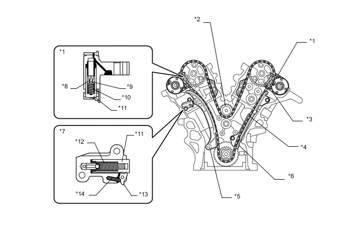
Text in Illustration *1 No. 2 Chain Tensioner Sub-assembly (Secondary) *2 Idle Sprocket Assembly *3 No. 2 Chain Sub-assembly (Secondary) *4 Chain Sub-assembly (Primary) *5 Chain Tensioner Slipper *6 No. 1 Chain Vibration Damper *7 No. 1 Chain Tensioner Sub-assembly (Primary) *8 Ball *9 Ball Spring *10 Main Spring *11 Plunger *12 Spring *13 Cam *14 Cam Spring
-
-
Valve Lash Adjuster Assembly
-
The lash adjusters, which are located at the fulcrum (pivot point) of the roller rocker arms, each consist primarily of a plunger, plunger spring, check ball, and check ball spring.
-
Both the engine oil that is supplied by the cylinder head and the built-in spring actuate the valve lash adjuster assembly. The oil pressure and the spring force that act on the plunger push the No. 1 valve rocker arm sub-assembly against the cam, in order to adjust the clearance between the valve stem and the No. 1 valve rocker arm. This prevents the generation of noise during the opening and closing of the valves. As a result, engine noise is reduced.
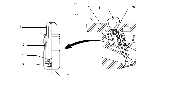
Text in Illustration *1 Plunger *2 Oil Passage *3 Check Ball *4 Check Ball Spring *5 Plunger Spring *6 Valve Lash Adjuster Assembly *7 Oil Passage *8 Cam *9 No. 1 Valve Rocker Arm Sub-assembly - -
-
-
Timing Chain Cover Sub-assembly
The timing chain cover sub-assembly has an integrated construction that includes the oil pump assembly and engine water pump assembly. Thus, the number of parts has been reduced, resulting in a weight reduction.
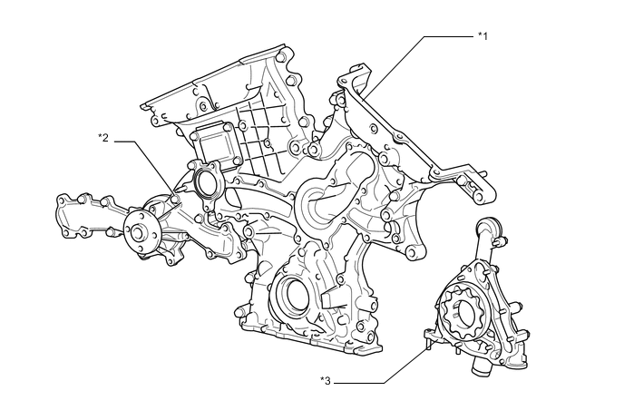
Text in Illustration *1 Timing Chain Cover Sub-assembly *2 Engine Water Pump Assembly *3 Oil Pump Assembly - - -
V-ribbed Belt
-
Accessory components are driven by a serpentine belt consisting of a single V-ribbed belt. This reduces the overall engine length, weight and number of engine parts.
-
The automatic tensioner eliminates the need for tension adjustment.
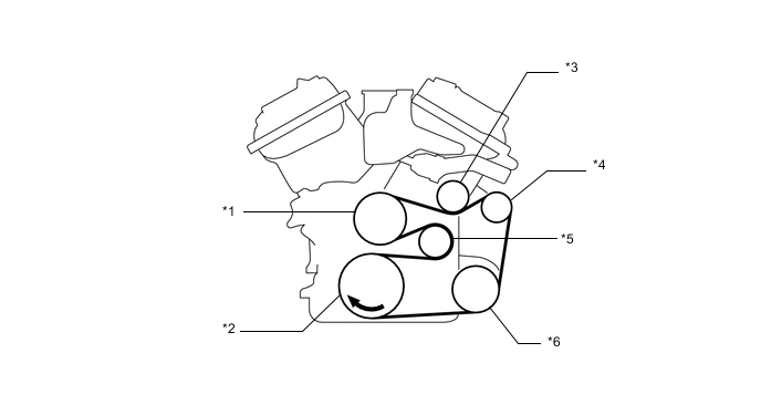
Text in Illustration *1 Water Pump Pulley *2 Crankshaft Pulley *3 No. 2 Idler Pulley Sub-assembly *4 Generator Pulley *5 Idler Pulley for Automatic Tensioner *6 Air Conditioning Compressor Pulley
-
-
V-ribbed Belt Tensioner Assembly
-
The tension of the V-ribbed belt is properly maintained by the tension spring that is enclosed in the belt tensioner assembly.
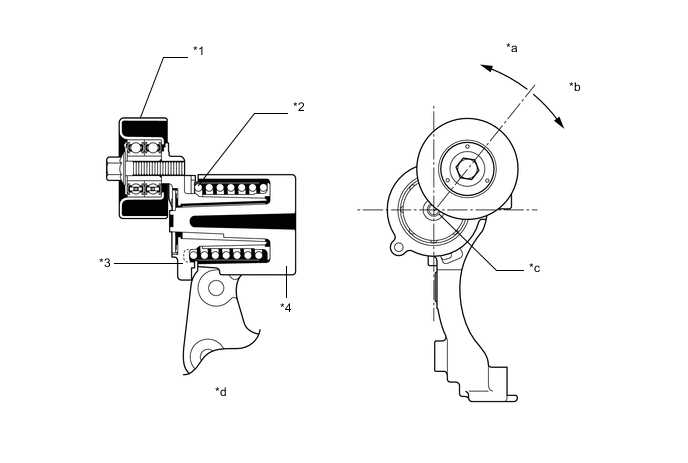
Text in Illustration *1 Idler Pulley *2 Spring *3 Arm *4 Bracket *a Force From Belt *b Belt Tension Direction *c Fulcrum *d Cross Section
-
-