ENGINE UNIT
-
CONSTRUCTION
-
Cylinder Head Cover Sub-assembly
-
A lightweight and high-strength aluminum cylinder head cover sub-assembly is used.
-
An oil delivery pipe is installed inside the cylinder head cover sub-assembly. This ensures lubrication to the sliding parts of the No. 1 valve rocker arm sub-assemblies, improving reliability.
-
An oil separator (ventilation case sub-assembly) is provided in the blow-by gas passage inside the cylinder head cover sub-assembly. This separates the engine oil from the blow-by gas in order to reduce oil degradation and reduce the amount of engine oil consumed.
-
Acrylic rubber, which excels in heat resistance and reliability, is used for the cylinder head cover gasket.
-
The camshaft timing oil control valve assembly is installed in the cylinder head cover sub-assembly. This simplifies oil passage.
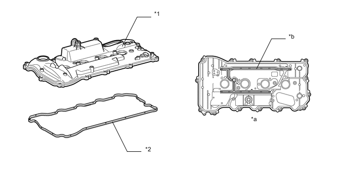
Text in Illustration *1 Cylinder Head Cover Sub-assembly *2 Cylinder Head Cover Gasket *a View from Bottom Side *b Oil Delivery Pipe
-
-
Cylinder Head Assembly
-
The cylinder head structure is simplified by separating the cam journal portion (camshaft housing sub-assembly) from the cylinder head sub-assembly.
-
The cylinder head sub-assembly, which is made of aluminum, contains pentroof-type combustion chambers. The spark plug is located in the center of the combustion chamber in order to improve the engine's anti-knock performance.
-
A taper squish combustion chamber is used to improve anti-knock performance and intake efficiency. In addition, engine performance and fuel economy are improved.
-
A long-nozzle type fuel injector assembly for port injection, which has a protruding design, is used to optimize the intake airflow. Also, the fuel injection angle and port shape are optimized in consideration of reducing fuel adhesion to achieve low fuel consumption and low emissions.
-
The shape of the intake port has been optimized, thus increasing the tumble flow and flow of air into the combustion chamber, and improving engine power and fuel economy.
-
The shape of the exhaust port has been optimized, thus making it easier for the engine to expel burnt gas, and improving engine power.
-
The valve lash adjuster assemblies are installed in the upper part of the cylinder head sub-assembly, creating a structure where the oil passage supplying oil to the valve lash adjuster assemblies are combined with the interior of the cylinder head sub-assembly.
-
The diameter of the intake and exhaust valve has increased, thus improving engine power.
-
The shape of the water jacket is optimized to reduce the temperature of combustion chamber components and minimize the temperature difference between cylinders. These two improvements achieve a high compression ratio, which achieves high torque, high engine output and low fuel consumption.
-
A sub-water jacket is used around the exhaust ports to improve the following:
-
Heater performance due to warm-up improvements
-
Fuel economy due to reduced friction
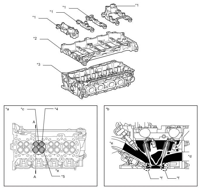
Text in Illustration *1 Camshaft Bearing Cap *2 Camshaft Housing Sub-assembly *3 Cylinder Head Sub-assembly *4 Exhaust Valve *5 Intake Valve - - *a View from Bottom Side *b A - A Cross Section *c Spark Plug Hole *d Exhaust Side *e Intake Side *f Taper Squish
-
-
-
Cylinder Head Gasket
-
A triple-layer metal type cylinder head gasket is used.
-
The surface of the cylinder head gasket is coated with fluorine rubber to ensure a high level of reliability.
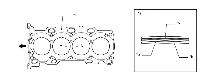
Text in Illustration *1 Cylinder Head Gasket - - *a A - A Cross Section *b Rubber 
Engine Front - -
-
-
Cylinder Block Sub-assembly
-
An aluminum cylinder block sub-assembly with a 11 mm (0.433 in.) distance between the cylinder bores is used to achieve a compact and lightweight configuration.
-
Water passages have been provided between the cylinder bores. By allowing the engine coolant to flow between the cylinder bores, this construction enables the temperature of the cylinder walls to be kept uniform.
-
The liners are a spiny-type, which have been manufactured so that their casting exteriors form large irregular surfaces in order to enhance the adhesion between the liners and the aluminum cylinder block sub-assembly. The enhanced adhesion helps heat dissipation, resulting in a lower overall temperature and reduced heat deformation of the cylinder bores.
-
A larger breather hole is provided in the No. 1 to No. 4 journal wall. As a result, friction is reduced and output performance is improved.
-
The basic structure of the engine, such as the thickness of the cylinder bore walls, the depth of the water jackets, and the cylinder block ribs has been optimized, reducing deviation from circularity of the cylinder bore, and thus reducing the friction, improving fuel consumption.
-
The angle of the bore cross hatching, the polishing on the cylinder liner surface, is at an angle of 15°, thus improving the oil retention of the interior of the cylinder bore. This reduces the friction between the cylinder bore and the piston, improving fuel consumption.
-
The shape of the ribs, and the positioning and shape of the knock control sensor have been optimized, thus improving control of knocking.
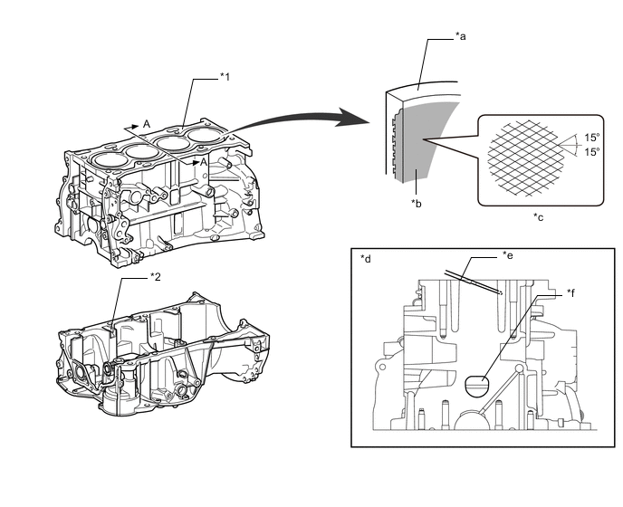
Text in Illustration *1 Cylinder Block Sub-assembly *2 Stiffening Crankcase Assembly *a Cylinder Bore *b Spiny-type Liner (Irregularly Shaped Outer Casting Surface of Liner) *c Bore Cross Hatch *d A - A Cross Section *e Water Passage *f Larger Breather Hole -
Through the use of an offset crankshaft, the centerline of the bores is shifted 10 mm (0.39 in.) towards the exhaust side in relation to the centerline of the crankshaft. Thus, the side force to the cylinder wall is reduced when the maximum pressure is applied. This contributes to fuel economy.
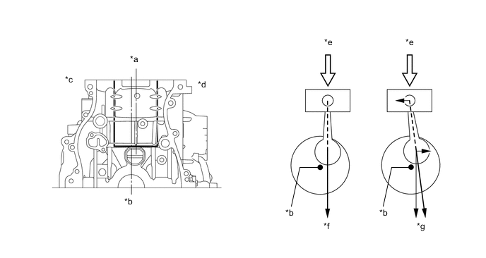
Text in Illustration *a Bore Centerline *b Crankshaft Center *c Intake Side *d Exhaust Side *e Maximum Pressure *f Offset Crankshaft *g Non-offset Crankshaft - - -
A shallow bottom water jacket is used. The resulting reduction in the volume of the engine coolant improves warm-up performance, which contributes to improved fuel economy.
-
A cylinder block water jacket spacer utilizing resin with excellent heat resistance and shaping precision is used.
-
A cylinder block water jacket spacer is provided in the water jacket of the cylinder block subassembly.
-
The cylinder block water jacket spacer suppresses the water flow in the bottom of the water jackets, guides the coolant in the upper area of the water jacket, and ensures uniform temperature distribution. As a result, the viscosity of the engine oil that acts as a lubricant between the bore walls and the pistons can be lowered, thus reducing friction. Additionally, the coolant intake at the left side of the No. 1 cylinder bore is covered, thus preventing the No. 1 cylinder bore from excessive cooling.
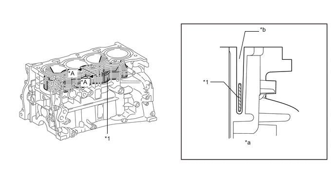
Text in Illustration *1 Cylinder Block Water Jacket Spacer - - *a A - A Cross Section *b Water Jacket
-
-
Stiffening Crankcase Assembly
-
A lightweight and high-strength aluminum die-cast stiffening crankcase assembly is used. This assembly is integrated with the cylinder block sub-assembly, thus improving the rigidity of the join with the transaxle, and reducing vibration and noise transmitted to the interior of the vehicle cabin.
-
Oil drain passages are provided in the stiffening crankcase assembly. This prevents the crankshaft from churning the engine oil, reducing rotational resistance.
-
A passage for introducing blowby gas into the oil separator is integrated into the stiffening crankcase assembly. Additionally, the passage uses a labyrinth structure to separate oil mist from the blowby gas, reducing oil consumption.
-
The high pressure oil passage, rear oil seal retainer, oil filter bracket and rear end plate are integrated with the stiffening crankcase assembly, thus reducing the weight of the engine and making it compact.
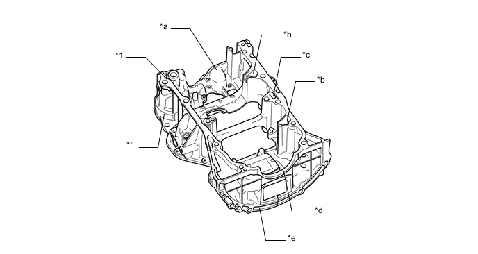
Text in Illustration *1 Stiffening Crankcase Assembly - - *a Oil Passage *b Blowby Gas Passage *c Oil Drain Passage *d Rear Oil Seal Retainer *e Rear End Plate *f Oil Filter Bracket
-
-
Piston
-
The pistons are made of aluminum alloy to allow them to be compact and lightweight.
-
The piston head portion uses a taper squish shape to achieve fuel combustion efficiency.
-
The piston skirts are coated with resin to reduce friction losses.
-
The groove of the No. 1 compression ring is coated with alumite to ensure abrasion resistance.
-
Low-tension piston rings are used to reduce friction and achieve excellent fuel economy.
-
Narrow-width piston rings are used to reduce weight and friction.
-
A Diamond Like Carbon (DLC) coating has been applied to the surface of the No. 1 compression ring, in order to improve wear resistance.
-
A No. 1 compression ring with an inside bevel shape is used to improve engine performance.
-
A steel No. 2 compression ring is used to improve wear resistance.
-
A groove is added to the inner surface of the oil ring rail, thus making the engine oil easy to discharge and reduce oil consumption.
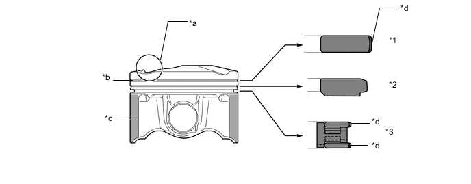
Text in Illustration *1 No. 1 Compression Ring *2 No. 2 Compression Ring *3 Oil Ring - - *a Taper Squish Shape *b Alumite Coating *c Resin Coating *d DLC Coating
-
-
Connecting Rod and Connecting Rod Bearing
-
Connecting rod sub-assemblies that have been forged for high strength are used for weight reduction.
-
Knock pins are used at the mating surfaces of the connecting rod caps to minimize the shifting of the connecting rod caps during assembly.
-
A small end bushing, which uses a material that can withstand high pressures, is used to improve reliability.
-
Plastic region tightening bolts are used for the connecting rod sub-assemblies.
-
Aluminum bearings are used for the connecting rod bearings.
-
Resin coated aluminum connecting rod bearings are used for the connecting rod bearings. The connecting rod bearings are reduced in width to reduce friction.
-
Lead-free materials have been used for the connecting rod sub-assembly, small end bushing, connecting rod bearing and connecting rod bolt in consideration of environmental issues.
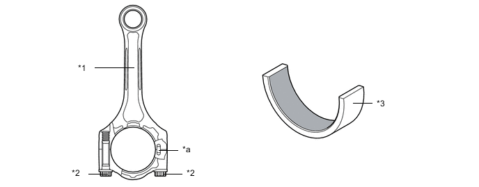
Text in Illustration *1 Connecting Rod Sub-assembly *2 Plastic Region Tightening Bolt *3 Connecting Rod Bearing - - *a Knock Pin - - 
Resin Coating - -
-
-
Crankshaft
-
A crankshaft made of forged steel, which excels in rigidity and wear resistance, is used.
-
The crankshaft has 5 main bearing journals and 8 balance weights.
-
A balance shaft drive gear is provided on the crankshaft.
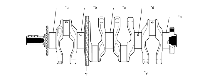
Text in Illustration *a No. 1 Main Bearing Journal *b No. 2 Main Bearing Journal *c No. 3 Main Bearing Journal *d No. 4 Main Bearing Journal *e No. 5 Main Bearing Journal *f Balance Shaft Drive Gear *g Balance Weight - -
-
-
Crankshaft Bearing
-
The oil groove on the crankshaft bearing is made eccentric to reduce the amount of oil leakage from the bearing. This enables the capacity of the oil pump to be reduced in order to reduce parasitic losses.
-
Resin coated aluminum crankshaft bearings are used for the crankshaft bearings. The crankshaft bearings are reduced in width to reduce friction.
-
Lead-free materials have been used for the crankshaft and crankshaft bearing in consideration of environmental issues.
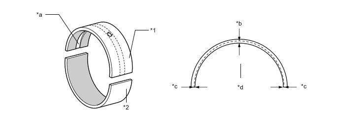
Text in Illustration *1 Upper Main Bearing (Crankshaft Bearing) *2 Lower Main Bearing (Crankshaft Bearing) *a Oil Groove *b Center *c Edge *d Oil Groove Depth Resin Coating - -
-
-
Balance Shaft
-
An engine balancer assembly is used to reduce vibration. An engine balancer assembly is used to reduce vibration. The inertial mass of the weight inside the engine balancer assembly is optimized, reducing the muffled sound inside the vehicle cabin.
-
The crankshaft directly drives the No. 1 balance shaft.
-
In addition, a resin gear is used on the driven side to suppress noise and offer a lightweight design.
-
The engine balancer assembly is separated from the stiffening crankcase assembly, thus making it easier to be serviced. Additionally, the engine balancer assembly is fastened to the highly-rigid cylinder block sub-assembly with bolts through the stiffening crankcase assembly, reducing the weight of the stiffening crankcase assembly, noise and vibrations.
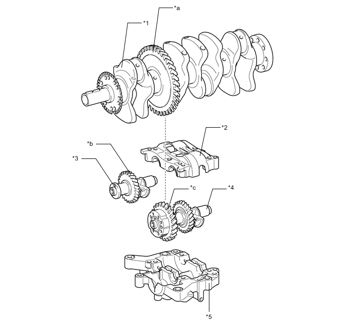
Text in Illustration *1 Crankshaft *2 No. 2 Balance Shaft Housing *3 No. 2 Balance Shaft *4 No. 1 Balance Shaft *5 No. 1 Balance Shaft Housing - - *a Balance Shaft Drive Gear *b Resin Gear *c Balance Shaft Driven Gear (Resin Gear) - - -
In an in-line 4-cylinder engine, the crankshaft angle for cylinders No. 1 and No. 4 is exactly the opposite (180°) from the position of cylinders No. 2 and No. 3. Therefore, the inertial force of the pistons and the connecting rods of the former 2 cylinders and of the latter 2 cylinders almost cancels each other out. However, because the position at which the piston reaches its maximum speed is located toward top dead center from the center of the stroke, the upward inertial force is greater than the downward inertial force. This unbalanced secondary inertial force is generated twice for each rotation of the crankshaft.
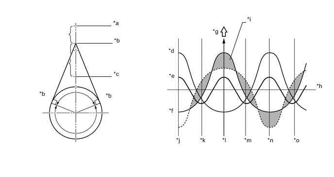
Text in Illustration (Inertial Force Generated by In-line 4 Cylinders:) *a Top Dead Center *b Point of Max. Speed *c Bottom Dead Center *d Inertial Force of Cylinders No. 2 and No. 3 *e Combined Inertial Force of All Cylinders (Unbalanced Secondary Inertial Force) *f Inertial Force of Cylinders No. 1 and No. 4 *g Force *h Crankshaft Angle *i Inertial force that cannot be canceled *j -180° *k -90° *l 0° *m 90° *n 180° *o 270° - - -
To cancel the unbalanced secondary inertial force, 2 balance shafts are provided that rotate twice for each rotation of the crankshaft. By doing this they generate an inertial force in the opposite direction. Also, in order to cancel the inertial force generated by the balance shafts themselves, there are actually 2 shafts rotating in opposite directions.
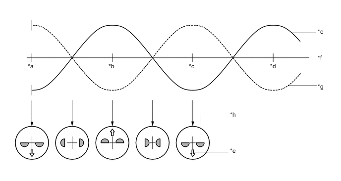
Text in Illustration (Inertial Force of Balance Shafts:) *a 0° *b 90° *c 180° *d 270° *e Inertial Force of Balance Shafts *f Crankshaft Angle *g Secondary Inertial Force *h Mass Direction of Balance Shaft
-
-
Valve Mechanism
-
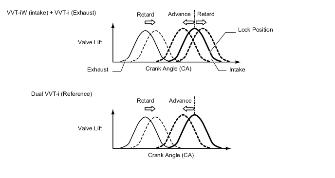
A high-expansion cycle (Atkinson cycle) is used to improve heat efficiency.
-
On the intake side, Variable Valve Timing-intelligent Wide (VVT-iW), which is provided with an intermediate lock mechanism that optimally controls the intake camshaft (camshaft) to the valve timings according to driving conditions, is used.
-
On the exhaust side, Variable Valve Timing-intelligent (VVT-i), which optimally controls the exhaust camshaft (No. 2 camshaft) to the valve timings according to driving conditions, is used.
-
The No. 1 valve rocker arm sub-assembly is used as a valve mechanism and by achieving size reduction while drastically reducing the amount of friction that occurs between the sliding parts and cams, low fuel consumption is achieved. Also, an oil pressure type valve lash adjuster assembly is used to make valve clearance adjustment unnecessary in consideration of serviceability.
-
A valve spring (inner compression spring), whose upper portion is shaped like a beehive, is used to reduce inertial mass. As a result, the load on the valve spring (inner compression spring) and friction are reduced.
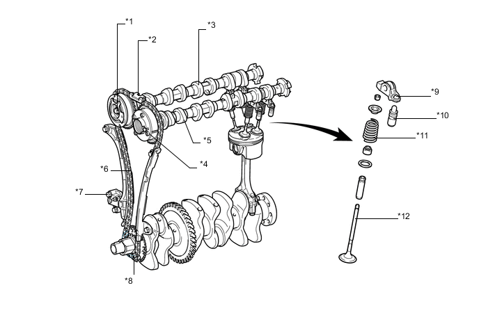
Text in Illustration *1 Camshaft Timing Gear Assembly *2 Timing Chain Guide *3 Intake Camshaft (Camshaft) *4 Camshaft Timing Exhaust Gear Assembly *5 Exhaust Camshaft (No. 2 Camshaft) *6 Chain Tensioner Slipper *7 No. 1 Chain Tensioner Assembly *8 Chain Sub-assembly *9 No. 1 Valve Rocker Arm Sub-assembly *10 Valve Lash Adjuster Assembly *11 Valve Spring (Inner Compression Spring) *12 Valve
-
-
Valve Timing
Intake camshaft Open -30 to 50° BTDC Close 110 to 30° ABDC Exhaust camshaft Open 60 to 5° BBDC Close 0 to 55° ATDC 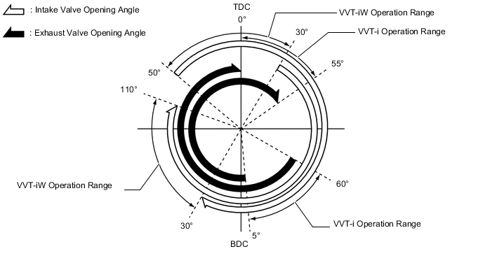
-
Camshaft
-
The camshafts are made of cast iron alloy.
-
An oil passage is provided in the intake camshaft (camshaft) and exhaust camshaft (No. 2 camshaft) in order to supply engine oil to the VVT-iW and VVT-i systems.
-
A VVT-i controller (camshaft timing gear assembly or camshaft timing exhaust gear assembly) is installed on the front of the intake camshaft (camshaft) and exhaust camshaft (No. 2 camshaft) to vary the timing of the intake and exhaust valves.
-
Together with the use of the No. 1 valve rocker arm sub-assemblies, the cam profile is modified. This results in increased valve lift when the valve begins to open and as it finishes closing, helping to achieve enhanced output performance.
-
A timing rotor for the camshaft position sensor is provided on the back of the intake camshaft (camshaft) and exhaust camshaft (No. 2 camshaft). Additionally, a cam for powering the fuel pump is installed on the intake camshaft, thus reducing the size of the engine.
-
The cam that drives the fuel pump assembly (for high pressure) is positioned directly above the No. 4 cylinder of the intake camshaft (camshaft) to achieve size reduction. Also, a pump cam with 4 peaks is used in the cam that drives the fuel pump assembly (for high pressure) and by synchronizing fuel pressure-feeding and fuel injection, the difference in fuel pressure between cylinders is reduced.
-
The vacuum pump assembly is driven by the end of the exhaust camshaft (No. 2 camshaft).
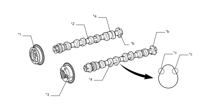
Text in Illustration *1 Camshaft Timing Gear Assembly *2 Intake Camshaft (Camshaft) *3 Camshaft Timing Exhaust Gear Assembly *4 Exhaust Camshaft (No. 2 Camshaft) *a Cam (for Powering the Fuel Pump) *b Timing Rotor *c Modified Portion of Cam Profile - -
-
-
Camshaft Timing Gear Assembly
-
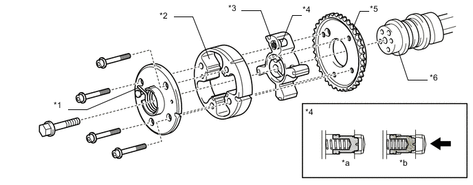
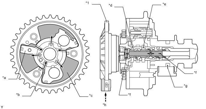
A 4-blade vane type VVT-iW controller (camshaft timing gear assembly) is used on the intake side.
-
2 lock pins are used to lock the vane during the intermediate phase of the VVT-iW operation range.
-
An assist spring, which assists torque in the advanced direction, is used so that the vane returns to the intermediate phase in response the intake camshaft (camshaft) torque fluctuations to securely connect the 2 lock pins. As a result, engine startability is ensured when starting the engine (when cranking) after the engine was stopped in the retarded operation state.
-
An oil control valve is built into the camshaft timing gear bolt, which secures the vane to the intake camshaft (camshaft). As a result, the controlled oil passage is shortened to improve response performance and operation at low temperatures. The oil control valve switches the oil passage when pressed by the cam timing oil control solenoid assembly. Oil passage switching is controlled to continuously change the intake camshaft (camshaft) phase.
-
The oil control valve has a structure which allows independent control of when the 2 lock pins are connected and released, separate from the advance control and retard control. As a result, a lock operation can be performed during the intermediate phase of the VVT-iW operation range.
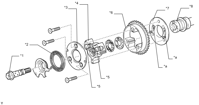
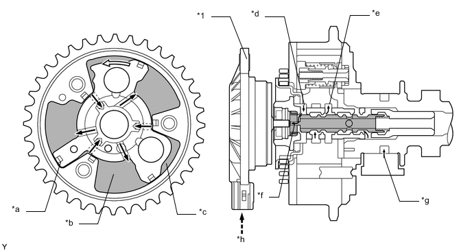
Text in Illustration (VVT-iW Controller (Camshaft Timing Gear Assembly):) *1 Camshaft Timing Gear Bolt *2 Assist Spring *3 Camshaft Timing Gear Cover FR *4 Vane (Fixed on Intake Camshaft (Camshaft)) *5 Lock Pin *6 Housing (Sprocket) *7 Camshaft Timing Gear Cover RR *8 Intake Camshaft (Camshaft) *a Ratchet Groove - - 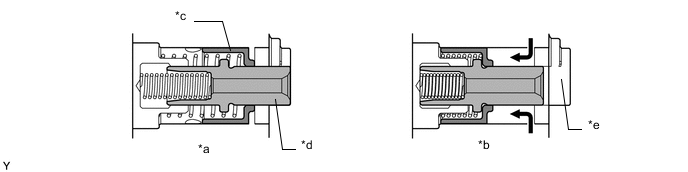
Text in Illustration (Lock Pin:) *a Lock Pin Connected *b Lock Pin Released *c Outer Pin *d Inner Pin *e Ratchet Groove - - Engine Oil - - 
Text in Illustration (Camshaft Timing Gear Bolt (built into Oil Control Valve): *a Drain *b To Advance Side Vane Chamber *c To Retard Side Vane Chamber *d Engine Oil *e To Lock Pin *f Oil Control Valve
-
-
Camshaft Timing Exhaust Gear Assembly
-
A 4-blade vane type VVT-i controller (camshaft timing exhaust gear assembly) is used on the exhaust side.
-
When the engine is stopped, a lock pin locks the exhaust camshaft at the most advanced position to ensure that the engine starts properly.
-
An advance assist spring is provided in the VVT-i controller (camshaft timing exhaust gear assembly) to assist the necessary torque in the advanced direction to keep the lock pin securely connected when the engine is stopped.
-
The ECM controls the amount of oil pressure applied to the advanced chamber and retarded chamber inside the VVT-i controller (camshaft timing exhaust gear assembly) based on signals from each sensor via the camshaft timing oil control valve assembly installed on the cylinder head cover sub-assembly and continuously changes the exhaust camshaft (No. 2 camshaft) phase.
Text in Illustration *1 Advance Assist Spring *2 Housing *3 Vane (Fixed on Exhaust Camshaft (No. 2 Camshaft)) *4 Lock Pin *5 Sprocket *6 Exhaust Camshaft (No. 2 Camshaft) *a At a Stop *b In Operation Oil Pressure - -
-
-
Valve Lash Adjuster
-
The valve lash adjuster assemblies, which are located at the fulcrum of the No. 1 valve rocker arm sub-assemblies, consist primarily of a plunger, a plunger spring, a check ball, and a check ball spring.
-
Engine oil supplied by the cylinder head sub-assembly and the built-in spring actuate the valve lash adjuster assembly. The oil pressure and the spring force that act on the plunger push the No. 1 valve rocker arm sub-assembly against the cam, adjusting the valve clearance created during the opening and closing of the valve. As a result, engine noise has been reduced.
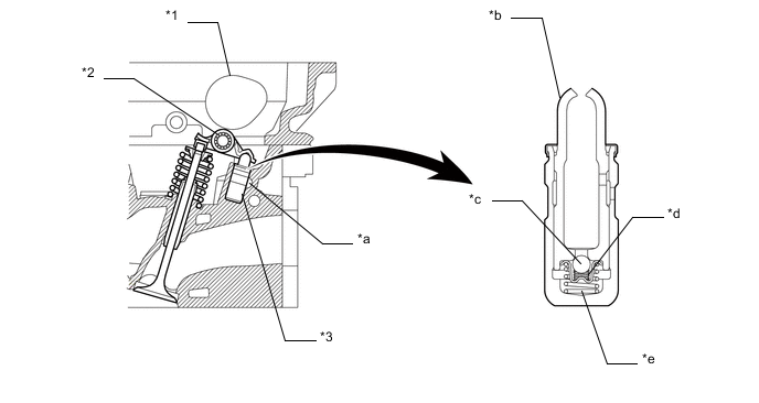
Text in Illustration *1 Cam *2 No. 1 Valve Rocker Arm Sub-assembly *3 Valve Lash Adjuster Assembly - - *a Oil Passage *b Plunger *c Check Ball *d Check Ball Spring *e Plunger Spring - - Tech Tips
Valve clearance adjustment is not necessary because a valve lash adjuster assembly is used.
-
-
Chain Sub-assembly and No. 1 Chain Tensioner Assembly
-
A roller chain with a 9.525 mm (0.375 in.) pitch is used.
-
The No. 1 chain tensioner assembly uses a spring and oil pressure to maintain proper chain tension at all times. The No. 1 chain tensioner assembly suppresses noise generated by the chain subassembly.
-
The No. 1 chain tensioner sub-assembly is a ratcheting type with a non-return mechanism.
-
To achieve excellent serviceability, the No. 1 chain tensioner assembly is constructed so that it can be removed and installed through a service hole in the timing chain cover sub-assembly.
-
The No. 1 chain vibration damper is installed between the camshaft sprockets on the intake and exhaust sides, thus reducing the vibration of the chain sub-assembly between the camshaft sprockets on the intake and exhaust sides when the engine is running, and ensuring that the engine is quiet and reliable.
-
The No. 1 chain tensioner sub-assembly is installed on the lower side, thus the engine is more compact.
-
Resin with excellent abrasion resistance is used on the shoes of the chain tensioner slipper, No. 1 chain vibration damper, and No. 1 chain vibration damper.
-
A gasket (chain tensioner gasket) is used for the No. 1 chain tensioner sub-assembly, improving the oil retention of the oil collector, and thus suppressing the action of the chain when the engine is starting. This makes the engine quieter.
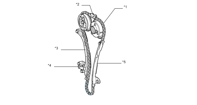
Text in Illustration *1 Chain Sub-assembly *2 Timing Chain Guide *3 Chain Tensioner Slipper *4 No. 1 Chain Tensioner Assembly *5 No. 1 Chain Vibration Damper - -
-
-
Timing Chain Cover Sub-assembly
-
An aluminum die-cast timing chain cover is used.
-
The timing chain cover sub-assembly has an integrated construction consisting of the oil pump and a timing chain oil jet. Thus, the number of parts has been reduced, resulting in a weight reduction.
-
The timing chain cover sub-assembly has a structure which allows the installation of a cam timing oil control solenoid assembly for VVT-iW control.
-
To achieve excellent serviceability, service holes for the No. 1 chain tensioner assembly and camshaft timing gear assembly are provided on the timing chain cover sub-assembly.
-
Stiffening ribs are optimally arranged on the rear side of the timing chain cover sub-assembly, making it easy for the engine oil to return to the sub-assembly. Engine vibration and noise reduction have also been balanced.
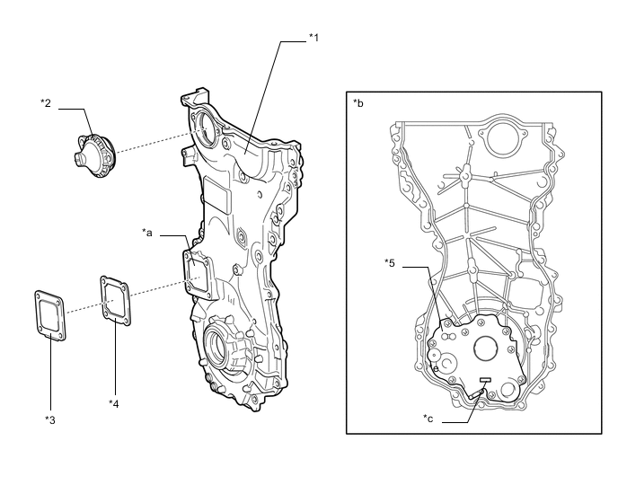
Text in Illustration *1 Timing Chain Cover Sub-assembly *2 Cam Timing Oil Control Solenoid Assembly *3 Timing Chain Cover Plate *4 Timing Chain Cover Gasket *5 Oil Pump - - *a Service Hole *b View from Rear Side *c Timing Chain Oil Jet - -
-
-
V-ribbed Belt
-
Accessory components are driven by a serpentine belt consisting of a single V-ribbed belt (fan and generator V belt). It reduces the overall engine length, weight and the number of engine parts.
-
An automatic V-ribbed belt tensioner assembly eliminates the need for tension adjustment.
-
The tension of the V-ribbed belt (fan and generator V belt) is properly maintained by the tension spring enclosed in the V-ribbed belt tensioner assembly.
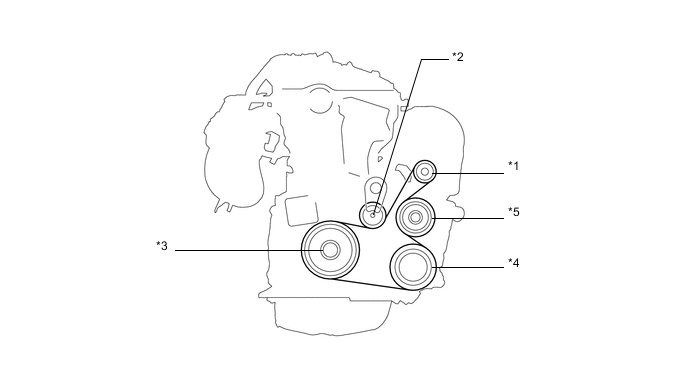
Text in Illustration *1 Generator Pulley *2 V-ribbed Belt Tensioner Assembly *3 Crankshaft Pulley *4 Air Conditioning Compressor Pulley *5 Engine Water Pump Pulley - -
-
-
-
OPERATION
-
Camshaft Timing Gear Assembly
-
Advance
-
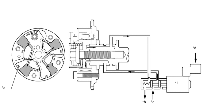
The cam timing oil control solenoid assembly operates according to the advance signal from the ECM. When the oil control valve reaches the position shown in the following illustration, the advance side vane chamber of the VVT-iW controller (camshaft timing gear assembly) is affected by oil pressure and the vane inside the VVT-iW controller (camshaft timing gear assembly) rotates in the advanced direction. The intake camshaft (camshaft) fixed to the vane also rotates to the advanced side.
Text in Illustration *1 Cam Timing Oil Control Solenoid Assembly - - *a Vane *b Retard Side Vane Chamber *c Advance Side Vane Chamber *d To Advance Side Vane Chamber *e From Retard Side Vane Chamber *f Drain *g Oil Pressure *h From ECM 
Rotation Direction - -
-
-
Retard
-
The cam timing oil control solenoid assembly operates according to the retard signal from the ECM. When the oil control valve reaches the position shown in the following illustration, the retard side vane chamber of the VVT-iW controller (camshaft timing gear assembly) is affected by oil pressure and the vane inside the VVT-iW controller (camshaft timing gear assembly) rotates in the retarded direction. The intake camshaft (camshaft) fixed to the vane also rotates to the retarded side.
Text in Illustration *1 Cam Timing Oil Control Solenoid Assembly - - *a Vane *b Retard Side Vane Chamber *c Advance Side Vane Chamber *d To Advance Side Vane Chamber *e From Retard Side Vane Chamber *f Drain *g Oil Pressure *h From ECM Rotation Direction - -
-
-
Hold
-
The ECM calculates the target advanced angle according to driving conditions and performs control. After setting the target timing, timings are maintained by the neutral oil control valve as long as driving conditions do not change. As a result, unnecessary engine oil discharge is suppressed while valve timings are aligned to the desired target position.
-
-
-
Camshaft Timing Exhaust Gear Assembly
-
Advance
-
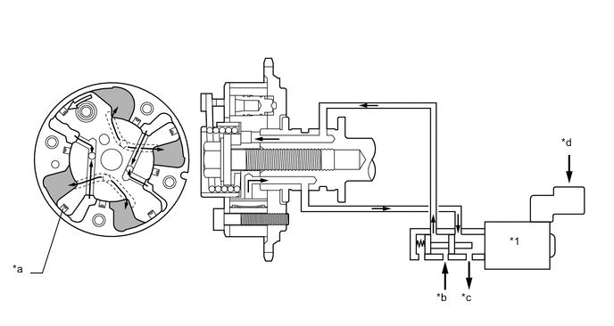
When the camshaft timing oil control valve assembly is positioned as shown in the illustration below by the advance signals from the ECM, the resultant oil pressure is applied to the timing advance side vane chamber to rotate the exhaust camshaft (No. 2 camshaft) in the timing advance direction.
Text in Illustration *1 Camshaft Timing Oil Control Valve Assembly - - *a Vane *b Drain *c Oil Pressure *d From ECM Rotation Direction - -
-
-
Retard
-
When the camshaft timing oil control valve assembly is positioned as shown in the illustration below by the retard signals from the ECM, the resultant oil pressure is applied to the timing retard side vane chamber to rotate the exhaust camshaft (No. 2 camshaft) in the timing retard direction.
Text in Illustration *1 Camshaft Timing Oil Control Valve Assembly - - *a Vane *b Oil Pressure *c Drain *d From ECM Rotation Direction - -
-
-
Hold
-
The ECM calculates the target advanced angle according to driving conditions and performs control. After setting the target timing, timings are maintained by the neutral camshaft timing oil control valve assembly as long as driving conditions do not change. As a result, unnecessary engine oil discharge is suppressed while valve timings are aligned to the desired target position.
-
-
-