ENGINE UNIT
-
CONSTRUCTION
-
Cylinder Head Cover Sub-assembly
-
A lightweight and high-strength magnesium cylinder head cover sub-assembly is used.
-
An oil delivery pipe is installed inside the cylinder head cover sub-assembly. This ensures lubrication to the sliding parts of the No. 1 valve rocker arm sub-assemblies, improving reliability.
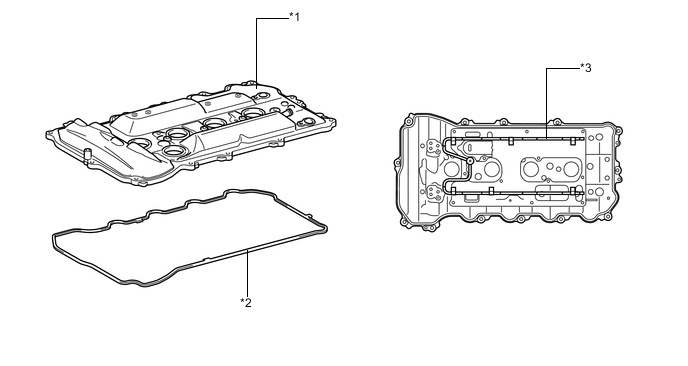
Text in Illustration *1 Cylinder Head Cover Sub-assembly *2 Cylinder Head Cover Gasket *3 Oil Delivery Pipe - -
-
-
Cylinder Head Gasket
-
A triple-layer metal type cylinder head gasket is used.
-
The surface of the cylinder head gasket is coated with fluorine rubber to ensure a high level of reliability.
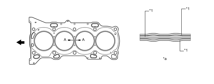
Text in Illustration *1 Fluorine Rubber - - *a A-A Cross Section - - 
Engine Front - -
-
-
Cylinder Head Sub-assembly
-
The cylinder head structure is simplified by separating the cam journal portion (camshaft housing sub-assembly) from the cylinder head.
-
The cylinder head sub-assembly, which is made of aluminum, contains pentroof-type combustion chambers. The spark plug is located in the center of the combustion chamber in order to improve the engine's anti-knock performance.
-
A taper squish combustion chamber is used to improve anti-knock performance and intake efficiency. In addition, engine performance and fuel economy are improved.
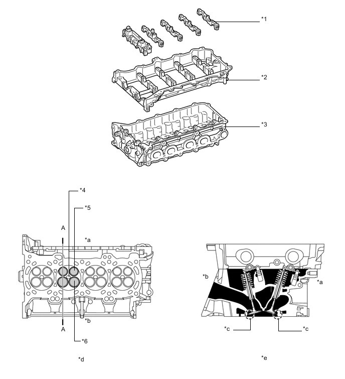
Text in Illustration *1 Camshaft Bearing Cap *2 Camshaft Housing *3 Cylinder Head Sub-assembly *4 Spark Plug Hole *5 Exhaust Valve *6 Intake Valve *a Exhaust Side *b Intake Side *c Taper Squish *d View from Bottom Side *e A-A Cross Section - -
-
-
Cylinder Block Sub-assembly
-
The cylinder block sub-assembly is made of aluminum alloy, so it is lightweight.
-
Water passages have been provided between the cylinder bores. By allowing the engine coolant to flow between the cylinder bores, this construction enables the temperature of the cylinder walls to be kept uniform.
-
The liners are a spiny-type, which have been manufactured so that their cast outers form large irregular surfaces in order to enhance the adhesion between the liners and the aluminum cylinder block sub-assembly. The enhanced adhesion helps heat dissipation, resulting in a lower overall temperature and reduced heat deformation of the cylinder bores.
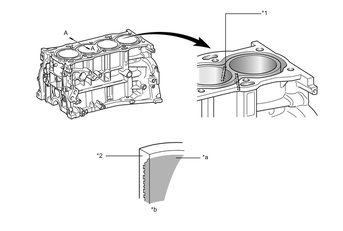
Text in Illustration *1 Water Passage *2 Cylinder Block *a Spiny-type Liner (Irregularly Shaped Outer Cast Surface of Liner) *b A-A Cross Section -
Blowby gas passages are provided in the crankcase.
-
Oil drain passages are provided in the crankcase. This prevents the crankshaft from churning the engine oil, reducing rotational resistance.
-
The oil filter bracket is integrated into the crankcase.
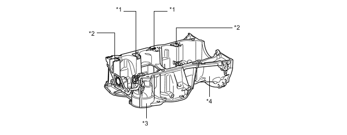
Text in Illustration *1 Blowby Gas Passage *2 Oil Drain Passage *3 Oil Filter Bracket *4 Crankcase -
An oil separator is provided in the blow-by gas passage inside the cylinder block sub-assembly. This separates the engine oil from the blow-by gas in order to reduce oil degradation and reduce the amount of engine oil consumed.
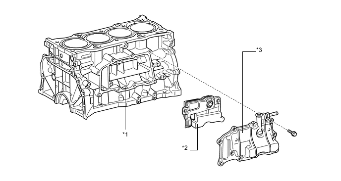
Text in Illustration *1 Oil Separator *2 Case Separator *3 Ventilation Case Sub-assembly - - -
Through the use of an offset crankshaft, the centerline of the bores is shifted 10 mm (0.39 in.) towards the exhaust side in relation to the centerline of the crankshaft. Thus, the side force to the cylinder wall is reduced when the maximum pressure is applied. This contributes to fuel economy.
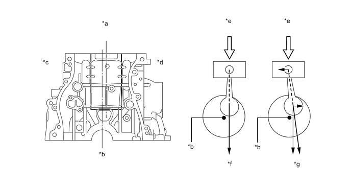
Text in Illustration *a Bore Centerline *b Crankshaft Centerline *c Intake Side *d Exhaust Side *e Maximum Pressure *f Offset Crankshaft *g Non-offset Crankshaft - - -
A shallow bottom water jacket is used. The resulting reduction in the volume of the engine coolant improves warm-up performance, which contributes to improved fuel economy.
-
A water jacket spacer is provided in the water jacket of the cylinder block sub-assembly.
-
The water jacket spacer suppresses the coolant flow in the bottom of the water jackets, guides the coolant in the upper area of the water jackets, water jacket to ensure ensures uniform temperature distribution. As a result, the viscosity of the engine oil that acts as a lubricant between the bore walls and the pistons can be lowered, thus reducing friction.
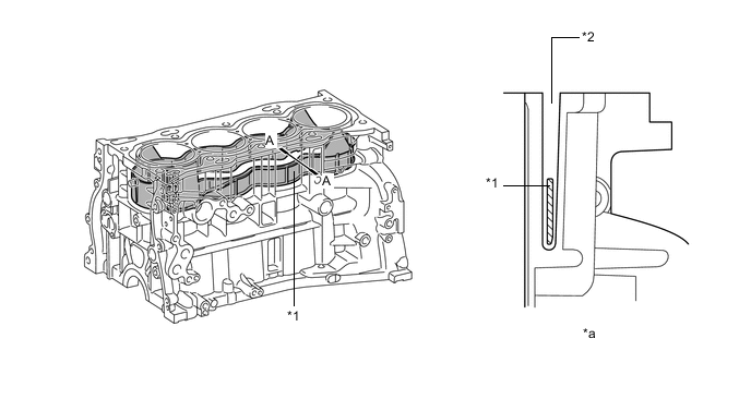
Text in Illustration *1 Water Jacket Spacer *2 Water Jacket *a A-A Cross Section - -
-
-
Piston
-
The pistons are made of aluminum alloy.
-
The tops of the pistons utilize a taper squish shape to achieve fuel combustion efficiency.
-
The piston skirts are coated with resin to reduce friction losses.
-
The groove of the No. 1 compression ring is coated with alumite to ensure abrasion resistance.
-
Low-tension piston rings are used to reduce friction and achieve excellent fuel economy.
-
Narrow-width piston rings are used to reduce weight and friction.
-
A Physical Vapor Deposition (PVD) coating has been applied to the surface of the No. 1 compression ring, in order to improve its wear resistance.
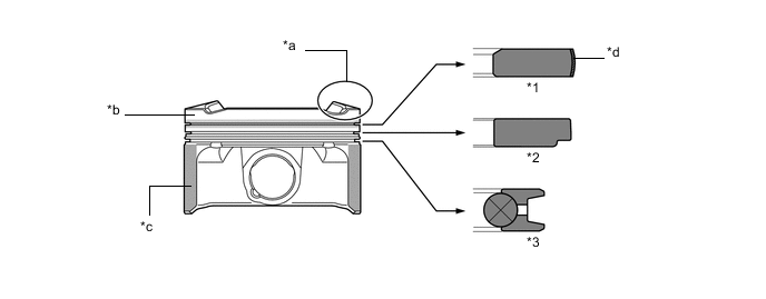
Text in Illustration *1 No. 1 Compression Ring *2 No. 2 Compression Ring *3 Oil Ring - - *a Taper Squish Shape *b Alumite Coating *c Resin Coating *d PVD Coating
-
-
Connecting Rod Sub-assembly
-
Connecting rod sub-assemblies that have been forged for high strength are used for weight reduction.
-
Knock pins are used at the mating surfaces of the connecting rod caps to minimize the shifting of the connecting rod caps during assembly.
-
Plastic region tightening bolts are used for the connecting rods.
-
Aluminum bearings are used for the connecting rod bearings.
-
The connecting rod bearings are reduced in width to reduce friction.
-
The lining surfaces of the connecting rod bearing are micro-grooved to achieve an optimal amount of oil clearance. As a result, cold-engine cranking performance has been improved and engine vibration has been reduced.
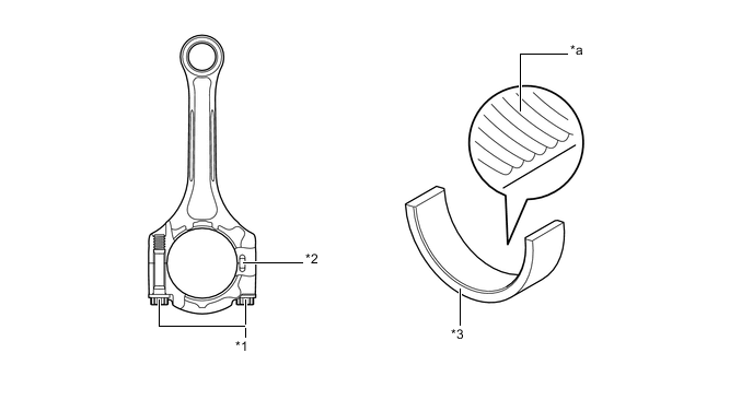
Text in Illustration *1 Plastic Region Bolt *2 Knock Pin *3 Connecting Rod Bearing - - *a Micro-grooved - -
-
-
Crankshaft
-
A crankshaft made of forged steel, which excels in rigidity and wear resistance, is used.
-
The crankshaft has 5 main bearing journals and 8 balance weights.
-
A balance shaft drive gear is provided on the crankshaft.
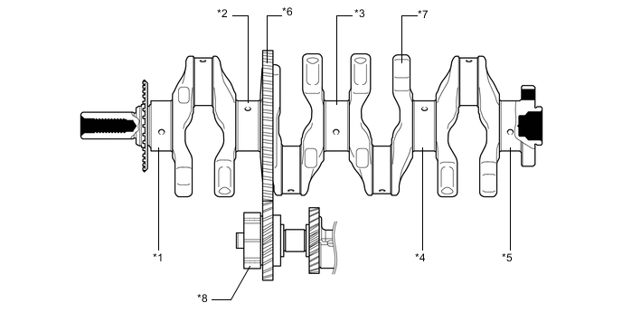
Text in Illustration *1 No. 1 Main Bearing Journal *2 No. 2 Main Bearing Journal *3 No. 3 Main Bearing Journal *4 No. 4 Main Bearing Journal *5 No. 5 Main Bearing Journal *6 Balance Shaft Drive Gear *7 Balance Weight *8 Balance Shaft
-
-
Crankshaft Bearing
-
The crankshaft bearings are reduced in width to reduce friction.
-
The lining surfaces of the crankshaft bearings are micro-grooved to achieve an optimal amount of oil clearance. As a result, cold-engine cranking performance has been improved and engine vibration has been reduced.
-
The oil groove on the crankshaft bearing is made eccentric to reduce the amount of oil leakage from the bearing. This enables the capacity of the oil pump to be reduced in order to reduce parasitic losses.
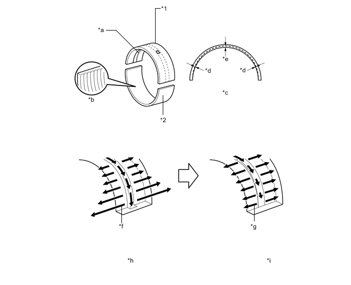
Text in Illustration *1 Upper Main Bearing *2 Lower Main Bearing *a Oil Groove *b Micro-grooved *c Oil Groove Depth *d Edge *e Center *f Large amount of oil leakage at end of groove *g Smaller amount of oil leakage at end of groove *h Conventional Oil Groove *i Off-center Oil Groove - -
-
-
Balance Shaft
-
Balance shafts are used to reduce vibration.
-
The crankshaft directly drives the No. 1 balance shaft.
-
In addition, a resin gear is used on the driven side to suppress noise and offer a lightweight design.
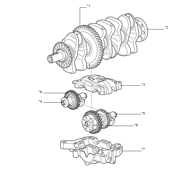
Text in Illustration *1 Balance Shaft Drive Gear *2 Crankshaft *3 No. 2 Balance Shaft Housing *4 No. 2 Balance Shaft *5 No. 1 Balance Shaft *6 Resin Gear *7 No. 1 Balance Shaft Housing - - -
In an in-line 4-cylinder engine, the crankshaft angle for cylinders No. 1 and No. 4 is exactly the opposite (180°) from the position of cylinders No. 2 and No. 3. Therefore, the inertial force of the pistons and the connecting rods of the former 2 cylinders and of the latter 2 cylinders almost cancels each other out. However, because the position at which the piston reaches its maximum speed is located toward top dead center from the center of the stroke, the upward inertial force is greater than the downward inertial force. This unbalanced secondary inertial force is generated twice for each rotation of the crankshaft.
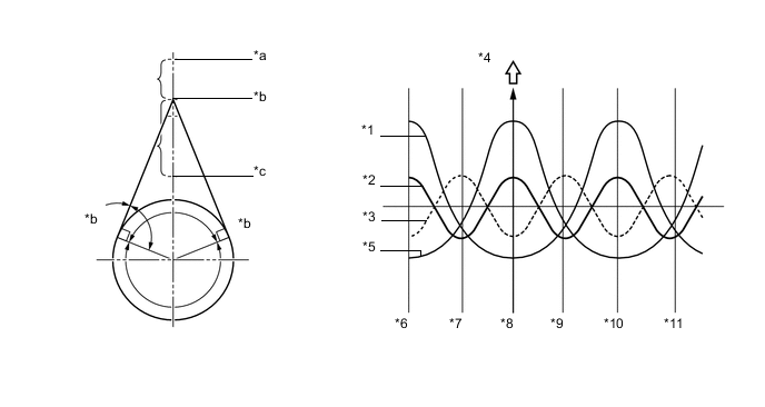
Text in Illustration (Inertial Force Generated by In-line 4 Cylinders:) *1 Inertial Force of Cylinders No. 2 and No. 3 *2 Combined Inertial Force of All Cylinders
(Unbalanced Secondary Inertial Force)
*3 Inertial Force of Engine Balancer Assembly *4 Force *5 Inertial Force of Cylinders No. 1 and No. 4 *6 -180° *7 -90° *8 0° *9 90° *10 180° *11 270° - - *a Top Dead Center *b Point of Max. Speed *c Bottom Dead Center - - -
To cancel the unbalanced secondary inertial force, 2 balance shafts are provided that rotate twice for each rotation of the crankshaft. By doing this they generate an inertial force in the opposite direction. Also, in order to cancel the inertial force generated by the balance shafts themselves, there are actually 2 shafts rotating in opposite directions.
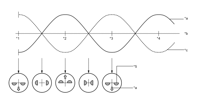
Text in Illustration (Inertial Force of Balance Shafts:) *1 0° *2 90° *3 180° *4 270° *5 Mass Direction of Balance Shaft - - *a Inertial Force of Balance Shafts *b Crankshaft Angle *c Secondary Inertial Force - -
-
-
Crankshaft Pulley
-
The rigidity of the crankshaft pulley with its built-in torsional damper rubber reduces noise.
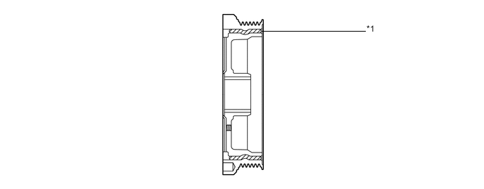
Text in Illustration *1 Torsional Damper Rubber - -
-
-
Valve Mechanism
-
Each cylinder of this engine has 2 intake valves and 2 exhaust valves. Intake and exhaust efficiency is increased due to the larger total port areas.
-
This engine uses the No. 1 valve rocker arm sub-assemblies with built-in needle bearings. This reduces the friction that occurs between the cams and the No. 1 valve rocker arm sub-assemblies that push the valves down, thus improving fuel economy.
-
Valve lash adjuster assemblies, which maintain a constant zero valve clearance through the use of oil pressure and spring force, are used.
-
The intake and exhaust camshafts are driven by a chain sub-assembly.
-
This engine has the dual Variable Valve Timing-intelligent (VVT-i) system which controls the intake camshaft and exhaust camshaft to provide optimal valve timing according to driving conditions. With the use of this system, lower fuel consumption, higher engine performance, and fewer exhaust emissions have been achieved.
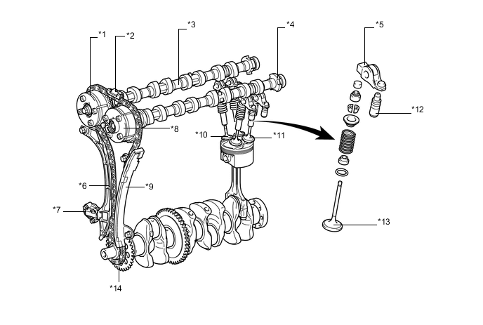
Text in Illustration *1 Camshaft Timing Gear Assembly *2 No. 2 Chain Vibration Damper *3 Camshaft *4 No. 2 Camshaft *5 No. 1 Valve Rocker Arm Sub-assembly *6 Chain Tensioner Slipper *7 No. 1 Chain Tensioner Assembly *8 Camshaft Timing Exhaust Gear Assembly *9 No. 1 Chain Vibration Damper *10 Intake Valve *11 Exhaust Valve *12 Valve Lash Adjuster Assembly *13 Valve *14 Chain Sub-assembly
-
-
Valve Timing
Intake camshaft Open 3° to 38° BTDC Close 61° to 26° ABDC Exhaust camshaft Open 60° to 25° BBDC Close 4° to 39° ATDC 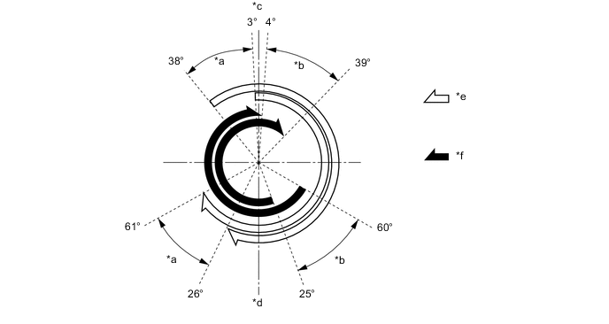
Text in Illustration *a VVT-i Operation Range (Intake) *b VVT-i Operation Range (Exhaust) *c TDC *d BDC *e Intake Valve Opening Angle *f Exhaust Valve Opening Angle -
Camshaft
-
The camshafts are made of cast iron alloy.
-
Oil passages are provided in the intake and exhaust camshafts in order to supply engine oil to the VVT-i system.
-
A camshaft timing gear assembly and camshaft timing exhaust gear assembly are installed on the front of their respective camshafts to vary the timing of the intake and exhaust valves.
-
Together with the use of the No. 1 valve rocker arm sub-assemblies, the cam profile is modified. This results in increased valve lift when the valve begins to open and as it finishes closing, helping to achieve enhanced output performance.
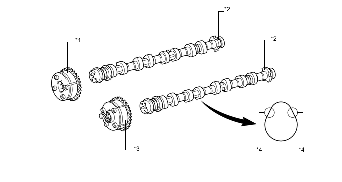
Text in Illustration *1 Camshaft Timing Gear Assembly *2 Timing Rotor *3 Camshaft Timing Exhaust Gear Assembly *4 Modified Portion of Cam Profile
-
-
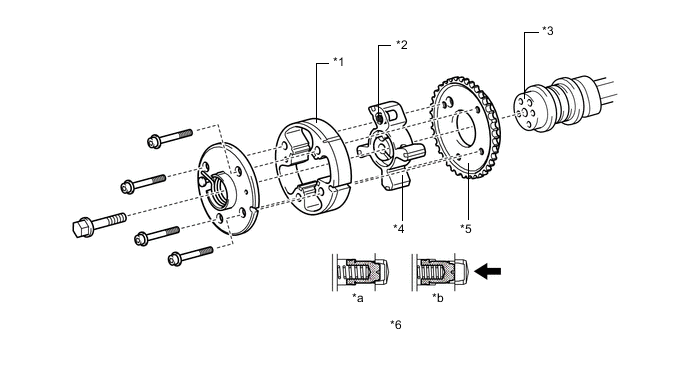
Camshaft Timing Gear Assembly
-
The camshaft timing gear assembly consists of an outer housing that is driven by the timing chain sprocket, and a vane sub-assembly that is coupled to the camshaft.
-
The camshaft timing gear assembly uses a vane with 4 lobes.
-
When the engine stops, the intake camshaft timing gear assembly is locked at the most retarded angle by its lock pin. This ensures excellent engine startability.
-
The oil pressure sent from the advance or retard side passages of the intake camshaft causes rotation of the vane sub-assembly relative to the timing chain sprocket, varying the valve timing continuously.
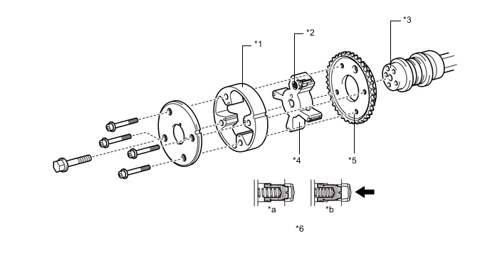
Text in Illustration *1 Housing *2 Lock Pin *3 Camshaft *4 Vane (Fixed on Intake Camshaft) *5 Sprocket *6 Lock Pin *a Engine Stopped *b Engine Operating Oil Pressure - -
-
-
Camshaft Timing Exhaust Gear Assembly
-
The camshaft timing exhaust gear assembly consists of an outer housing that is driven by the timing chain sprocket, and a vane sub-assembly that is coupled to the camshaft.
-
The camshaft timing exhaust gear assembly uses a vane with 4 lobes.
-
When the engine stops, the camshaft timing exhaust gear assembly is locked at the most advanced angle. This ensures excellent engine startability.
-
The oil pressure sent from the advance or retard side passages of the exhaust camshafts causes rotation of the vane sub-assembly relative to the timing chain sprocket, varying the valve timing continuously.
-
An advance assist spring is provided on the camshaft timing exhaust gear assembly. This helps to apply torque in the advance angle direction so that the vane lock pin securely engages with the housing when the engine stops.
Text in Illustration *1 Housing *2 Lock Pin *3 No. 2 Camshaft *4 Vane (Fixed on No. 2 Camshaft (Exhaust)) *5 Sprocket *6 Lock Pin *a Engine Stopped *b Engine Operating Oil Pressure - -
-
-
Chain Sub-assembly and No. 1 Chain Tensioner Assembly
-
A roller chain with a 9.525 mm (0.375 in.) pitch is used.
-
The No. 1 chain tensioner assembly uses a spring and oil pressure to maintain proper chain tension at all times. The chain tensioner suppresses noise generated by the chain sub-assembly.
-
The No. 1 chain tensioner sub-assembly is a ratcheting type with a non-return mechanism.
-
To achieve excellent serviceability, the No. 1 chain tensioner assembly is constructed so that it can be removed and installed through a service hole in the timing chain cover sub-assembly.
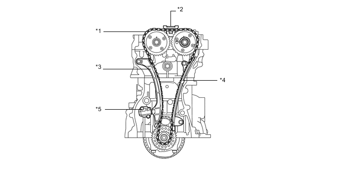
Text in Illustration *1 Chain Sub-assembly *2 No. 2 Chain Vibration Damper *3 Chain Tensioner Slipper *4 No. 1 Chain Vibration Damper *5 No. 1 Chain Tensioner Assembly - -
-
-
Valve Lash Adjuster Assembly
-
The hydraulic lash adjusters, which are located at the fulcrum (pivot point) of the No. 1 valve rocker arm sub-assemblies, each consists primarily of a plunger, plunger spring, check ball, and check ball spring.
-
Both the engine oil that is supplied by the cylinder head and the built-in spring actuate the valve lash adjuster assemblies. The oil pressure and the spring force that act on the plunger push the No. 1 valve rocker arm sub-assemblies against the cam in order to adjust the clearance between the valve stem and the No. 1 valve rocker arm sub-assembly. This prevents the generation of noise during the opening and closing of the valves. As a result, engine noise is reduced.
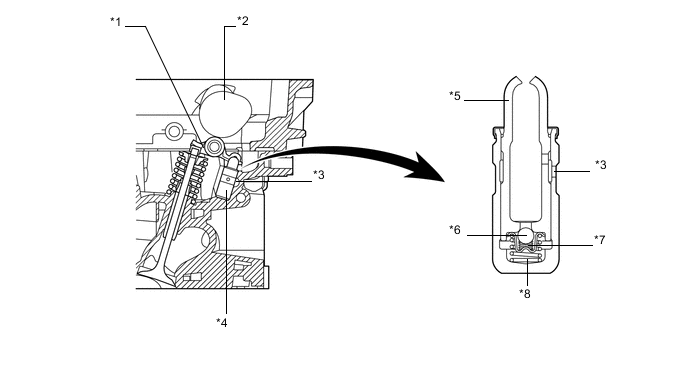
Text in Illustration *1 No. 1 Valve Rocker Arm Sub-assembly *2 Cam *3 Oil Passage *4 Valve Lash Adjuster Assembly *5 Plunger *6 Check Ball *7 Check Ball Spring *8 Plunger Spring
-
-
Timing Chain Cover Sub-assembly
-
An aluminum die-cast timing chain cover is used.
-
The timing chain cover has an integrated construction consisting of the oil pump and a timing chain oil jet. Thus, the number of parts has been reduced, resulting in a weight reduction.
-
To achieve excellent serviceability, service holes for the No. 1 chain tensioner assembly and camshaft timing gear assembly are provided on the timing chain cover sub-assembly.
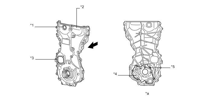
Text in Illustration *1 Service Hole (For Camshaft Timing Gear Assembly) *2 Timing Chain Cover Sub-assembly *3 Service Hole (For No. 1 Chain Tensioner Assembly) *4 Oil Pump *5 Timing Chain Oil Jet - - *a View from the rear - - Front - -
-
-
V-ribbed Belt
-
Accessory components are driven by a serpentine belt consisting of a single V-ribbed belt. It reduces the overall engine length, weight and number of engine parts.
-
The automatic tensioner eliminates the need for tension adjustment.
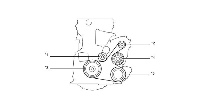
Text in Illustration *1 V-ribbed Tensioner Assembly *2 Generator Pulley *3 Crankshaft Pulley *4 Water Pump Pulley *5 Air Conditioning Compressor Pulley - -
-
-
V-ribbed Belt Tensioner Assembly
-
The tension of the V-ribbed belt is properly maintained by the tension spring that is enclosed in the belt tensioner.
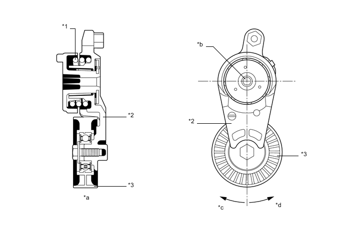
Text in Illustration *1 Spring *2 Arm *3 Idler Pulley - - *a Cross Section *b Fulcrum *c Force from Belt *d Belt Tension Direction
-
-