SFI SYSTEM
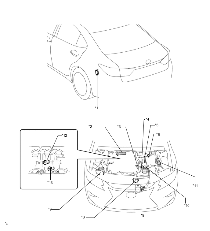
| *1 | Fuel Pump Control ECU Assembly | *2 | ACIS Actuator |
| *3 | Purge VSV | *4 | VSV (for Air Intake Control) |
| *5 | Air Cleaner Case Sub-assembly - Vacuum Tank |
*6 | Intake Mass Air Flow Meter Sub-assembly - Intake Air Temperature Sensor |
| *7 | Brake Actuator Assembly - Skid Control ECU |
*8 | Cooling Fan ECU |
| *9 | VSV (for Active Control Engine Mount) | *10 | Actuator (for Air Intake Control) |
| *11 | ECM | *12 | Knock Control Sensor (for Bank 1) |
| *13 | Knock Control Sensor (for Bank 2) | - | - |
| *a | The illustrations shown are examples only. | - | - |
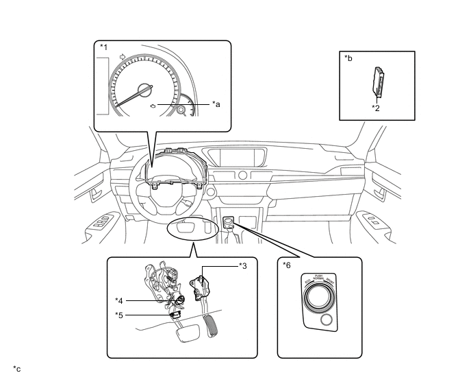
| *1 | Combination Meter Assembly | *2 | Certification ECU (Smart Key ECU Assembly) |
| *3 | Accelerator Pedal Sensor Assembly | *4 | Stop Light Switch Assembly |
| *5 | DLC3 | *6 | Integration Control and Panel Assembly - Drive Mode Select |
| *a | Refer to Service Bulletin for the installation position of the part. | *b | Malfunction Indicator Lamp (MIL) |
| *c | The illustrations shown are examples only. | - | - |
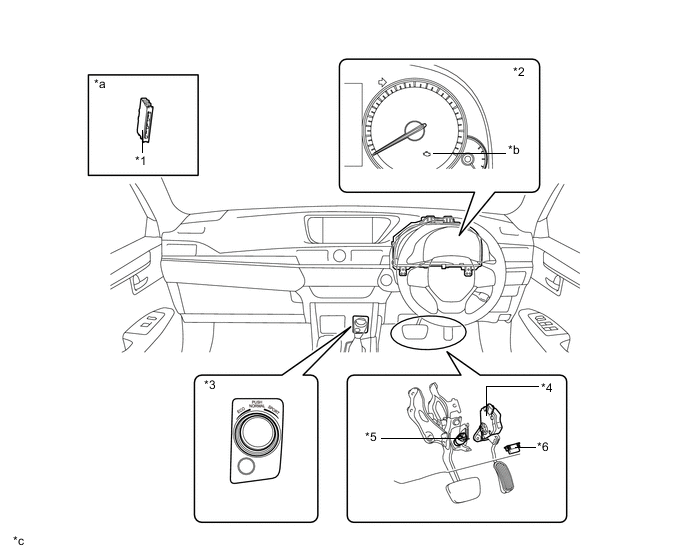
| *1 | Certification ECU (Smart Key ECU Assembly) | *2 | Combination Meter Assembly |
| *3 | Integration Control and Panel Assembly - Drive Mode Select |
*4 | Accelerator Pedal Sensor Assembly |
| *5 | Stop Light Switch Assembly | *6 | DLC3 |
| *a | Malfunction Indicator Lamp (MIL) | *b | Refer to Service Bulletin for the installation position of the part. |
| *c | The illustrations shown are examples only. | - | - |
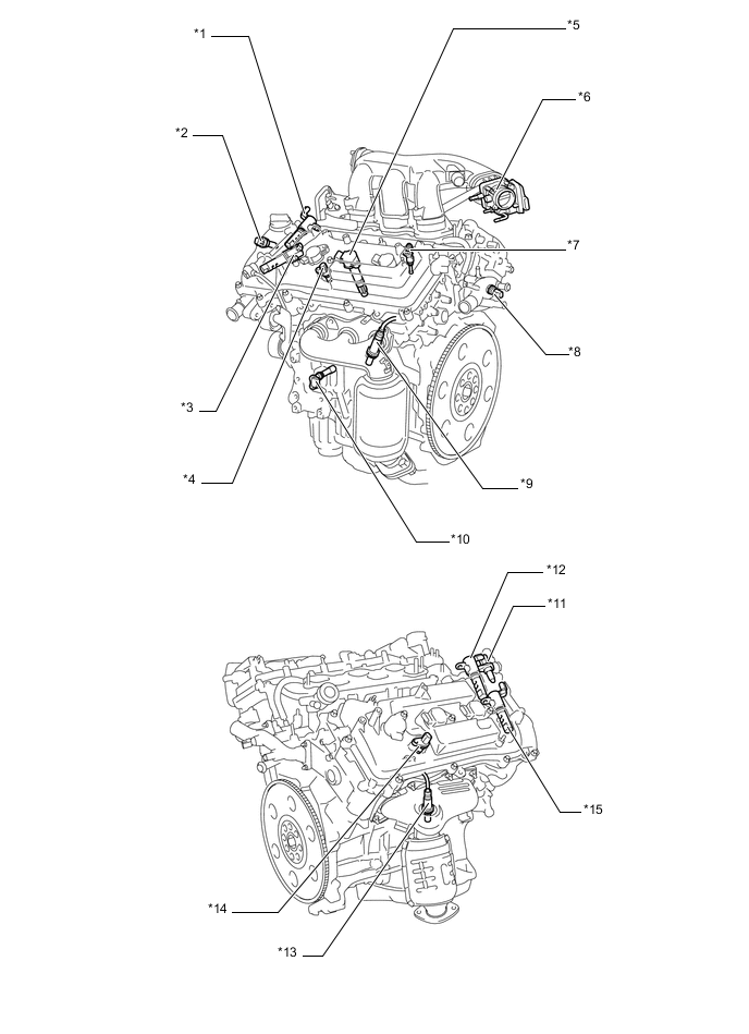
| *1 | Cam Timing Oil Control Valve Assembly (Bank 2 Intake Side) | *2 | Camshaft Position Sensor (Bank 2 Intake Side) |
| *3 | Cam Timing Oil Control Valve Assembly (Bank 2 Exhaust Side) | *4 | Camshaft Position Sensor (Bank 2 Exhaust Side) |
| *5 | Ignition Coil Assembly (with Igniter) | *6 | Throttle Body with Motor Assembly - Throttle Position Sensor - Throttle Control Motor |
| *7 | Fuel Injector Assembly | *8 | E. F. I. Engine Coolant Temperature Sensor |
| *9 | Air Fuel Ratio Sensor (Bank 2, Sensor 1) | *10 | Crank Position Sensor |
| *11 | Camshaft Position Sensor (Bank 1 Intake Side) | *12 | Cam Timing Oil Control Valve Assembly (Bank 1 Intake Side) |
| *13 | Air Fuel Ratio Sensor (Bank 1, Sensor 1) | *14 | Camshaft Position Sensor (Bank 1 Exhaust Side) |
| *15 | Cam Timing Oil Control Valve Assembly (Bank 1 Exhaust Side) | - | - |
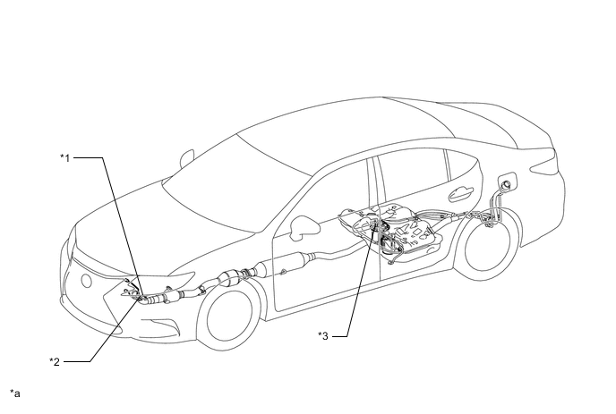
| *1 | Oxygen Sensor (Bank 1, Sensor 2) | *2 | Oxygen Sensor (Bank 2, Sensor 2) |
| *3 | Fuel Suction Tube with Pump and Gauge Assembly | - | - |
| *a | The illustration shown is an example only. | - | - |