SFI SYSTEM
-
FUNCTION OF MAIN COMPONENTS
-
The main components of the engine control system are as follows:
Component Outline Quantity Function ECM VFOREST + VFOREST 1 The ECM optimally controls the SFI, ESA and ETCS-i to suit the operating conditions of the engine in accordance with the signals provided by the sensors. Mass Air Flow Meter Subassembly Mass Air Flow Meter Silicon Chip Type 1 This sensor has a built-in silicon chip to directly detect the intake air mass. Intake Air Temperature Sensor Thermistor Type 1 This sensor detects the intake air temperature by means of an internal thermistor. Engine Coolant Temperature Sensor Thermistor Type 1 This sensor detects the engine coolant temperature. Temperature Sensor Thermistor Type 1 This sensor detects the engine oil temperature. Fuel Pressure Sensor Semiconductor Type 1 The sensor senses the fuel pressure in the fuel delivery pipe sub-assembly (for direct injection). Oil Pressure Sender Gauge Assembly Semiconductor Type 1 This gauge detects the engine oil pressure. Crankshaft Position Sensor [No. of Rotor Teeth] Magneto- Resistance Element (MRE) [36 - 2] 1 This sensor detects the engine speed and crankshaft angle. Camshaft Position Sensor (Intake Camshaft) [No. of Rotor Teeth] Magneto- Resistance Element (MRE) Type [3] 1
-
This sensor performs cylinder identification.
-
This sensor is used to detect the intake camshaft position.
Camshaft Position Sensor (Exhaust Camshaft) [No. of Rotor Teeth] Magneto- Resistance Element (MRE) Type [3] 1
-
This sensor performs cylinder identification.
-
This sensor is used to detect the exhaust camshaft position.
Manifold Absolute Pressure Sensor Semiconductor Silicon Chip Type 1 This sensor detects the pressure in the intake manifold and sends signals to the ECM. Throttle Body with Motor Assembly Throttle Position Sensor Linear (Non-contact) Type 1 This sensor detects the throttle valve opening angle. Throttle Control Motor DC Motor 1 This motor regulates the opening of the throttle valve in accordance with signals from the ECM. Knock Control Sensor Built-in Piezoelectric Type (Non-resonant Type/Flat Type) 1 This sensor detects engine knocking indirectly through the vibration of the cylinder block caused by engine knocking. Air Fuel Ratio Sensor Heated Type (Planar Type) 1 As with the heated oxygen sensor, this sensor detects the oxygen concentration in the exhaust gas. However, it detects the oxygen concentration in the exhaust gas linearly. Heated Oxygen Sensor Heated Type (Cup Type) 1 This sensor detects the oxygen concentration in the exhaust gas by measuring the electromotive force which is generated in the sensor itself. Camshaft Timing Oil Control Valve Assembly Solenoid Type 1 This solenoid changes the oil passage to the camshaft timing exhaust gear assembly in response to signals from the ECM. Cam Timing Oil Control Solenoid Assembly Solenoid Type 1 This solenoid controls the intake camshaft phase to achieve the optimal valve timing by moving the oil control valve. Fuel Injector Assembly For Port Injection 12-hole Type 4 The injector is an electromagnetically-operated nozzle which injects fuel in accordance with signals from the ECM. For Direct Injection High Pressure Single Slit Nozzle Type 4 This injector contains a high-pressure electromagnetically-operated nozzle to inject fuel directly into the cylinder. Ignition Coil Assembly Type with Igniter 4 This ignition coil assembly incorporates an igniter and provides high voltage necessary for ignition in accordance with signals from the ECM. Spark Plug Iridium-tipped Type 4 This spark plug produces a spark inside the cylinder using high voltage electricity delivered from the ignition coil assembly. EGR Valve Assembly Step Motor Type 1 This valve opens and closes based on signals from the ECM and controls the flow rate of the exhaust gas in the EGR bypass. -
-
-
SYSTEM CONTROL
-
The engine control system of the 6AR-FSE engine has the following features:
System Outline Direct Injection 4-stroke Gasoline Engine Superior Version Sequential Multiport Fuel Injection (D-4S SFI)
-
This is an L-type SFI system. It directly detects the intake air volume with a silicon chip type mass air flow meter sub-assembly.
-
The D-4S SFI system is a fuel injection system which combines direct injection injectors and port injection injectors.
-
Based on signals from each sensor, the ECM controls the injection volume and timing of each type of injector (direct and port injection types) in accordance with the engine speed and engine load in order to optimize combustion conditions.
Electronic Spark Advance (ESA)
-
Ignition timing is determined by the ECM based on signals from various sensors. The ECM corrects ignition timing in response to engine knocking.
-
This system determines the optimal ignition timing in accordance with the signals received from the sensors and sends ignition (IGT) signals to the igniters.
Electronic Throttle Control System-intelligent (ETCS-i) Optimally controls the opening angle of the throttle valve in accordance with the accelerator pedal input and the engine and vehicle operating conditions. Variable Valve Timing-intelligent Wide (VVT-iW) Regulates operation of the intake camshaft to ensure an optimal valve timing in accordance with the engine operating conditions. Variable Valve Timing-intelligent (VVT-i) Regulates operation of the exhaust camshaft to ensure an optimal valve timing in accordance with the engine operating conditions. Fuel Pump Control For High-pressure Pump Regulates the fuel pressure within a range of 4 to 20 MPa in accordance with driving conditions. For Low-pressure Pump
-
Fuel pump operation is controlled by signals from the fuel pump control ECU assembly.
-
The fuel pump is stopped when an SRS airbag is deployed in a frontal or side collision.
Cooling Fan Control Controls the radiator cooling fan operation in accordance with signals from the ECM based on the engine coolant temperature sensor signal and the operating condition of the air conditioning. Cranking Hold Function (Starter Control) Once the engine switch is pushed, this control operates the starter until the engine starts. Air Fuel Ratio Sensor and Heated Oxygen Sensor Heater Control Maintains the temperature of the air fuel ratio sensor or heated oxygen sensor at an appropriate level to increase the ability of each sensor to accurately detect the concentration of oxygen. EGR Control Based on the signals received from the sensors, the ECM determines the EGR volume in accordance with the engine operating conditions. Evaporative Emission Control The ECM controls the purge flow of evaporative emissions (HC) from the canister in accordance with the engine operating conditions. Brake Override System The driving torque is restricted when both the accelerator and brake pedals are depressed. (For the Activation Conditions and Inspection Method, refer to the repair manual) Drive Start Control System Even if the driver is in a hurry and abnormal accelerator pedal and shift operations are performed, vehicle speed and acceleration are restricted. Fail-safe When the ECM detects a malfunction, the ECM stops or controls the engine according to the data already stored in memory. Diagnosis When the ECM detects a malfunction, the ECM records the malfunction and information that relates to the fault. -
-
-
FUNCTION
-
D-4S SFI
-
The D-4S system is a fuel injection system which combines direct injection injectors and port injection injectors.
-
The mass air flow meter sub-assembly detects intake air volume to control fuel injection volume.
-
Based on signals from each sensor, the ECM controls the injection volume and timing of each type of fuel injector assembly (direct and port injection types) in accordance with engine load and engine speed in order to optimize combustion conditions.
-
To promote warm-up of the catalyst after a cold engine start, this system uses a stratified air fuel mixture. This creates an area near the spark plug that is richer than the rest of the air fuel mixture. This also allows a greater amount of ignition timing retard to be used, raising the exhaust gas temperature. The increased exhaust gas temperatures promote rapid warm-up of the catalysts, significantly reducing exhaust emissions.
-
When the engine is idling after warm-up, the fuel injector assembly (for port injection) is used to inject fuel, ensuring quietness.
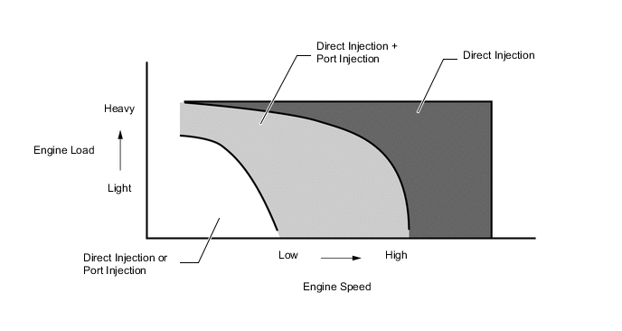
Figure 1. Fuel Injection System Activation Ranges:
-
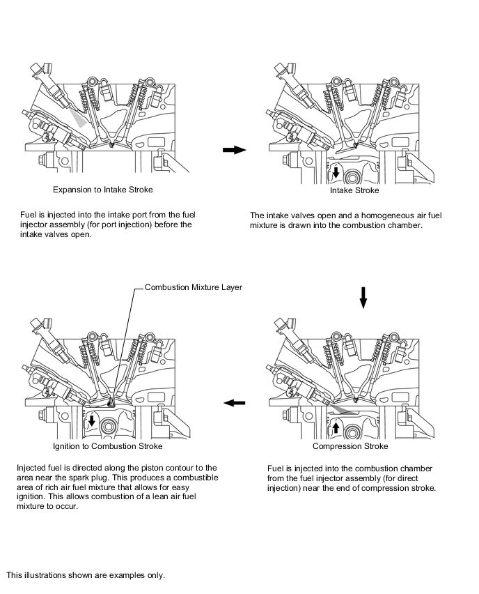
Stratified Combustion: To achieve stratified combustion, immediately after a cold engine start, fuel is injected into the intake port from the fuel injector assembly (for port injection) during the exhaust stroke. Fuel is also injected from the fuel injector assembly (for direct injection) near the end of the compression stroke. This results in an air fuel mixture that is stratified, and the area near the spark plug is richer than the rest of the air fuel mixture. This allows a retarded ignition timing to be used, raising the exhaust gas temperature. The increased exhaust gas temperatures promote rapid warm up of the catalysts, and significantly improve exhaust emission performance.
-
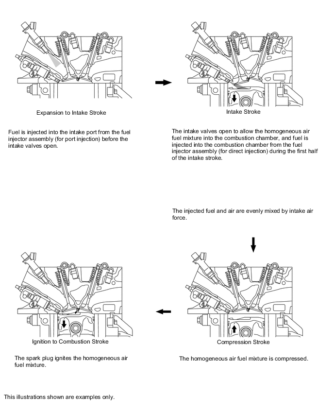
Homogeneous Combustion: To optimize combustion conditions, the ECM controls injection volume and timing of the fuel injector assemblies (for port injection) which inject fuel into the intake ports during the expansion, exhaust, and intake strokes. The ECM also controls the injection volume and timing of the fuel injector assemblies (for direct injection) which inject fuel during the first half of the intake stroke. The homogeneous air fuel mixture is created by either combined or individual use of the 2 different types of injectors. This allows utilization of the evaporation heat of the injected fuel to cool the compressed air, and it also allows an increase of charging efficiency and power output.
-
Air Fuel Ratio Control
-
Fuel injection volume is determined based on the engine speed and the intake air volume. In addition, feedback control is performed for the air fuel ratio after engine start based on the signal from the air fuel ratio sensor.
Control Combustion State Air Fuel Ratio Injection Timing* Precondition Lean air fuel ratio control Stratified Combustion 15 to 17 : 1 Compression Stroke Immediately after cold engine start Stoichiometric air fuel ratio control Homogeneous Combustion 14 to 15 : 1 Intake Stroke Low to mid-load driving Air fuel ratio feedback control prohibition Homogeneous Combustion - Intake Stroke High-load driving Cold engine *: Of the fuel injector assembly (for direct injection). The fuel injector assembly (for port injection) performs respective control to inject fuel from the expansion stroke to the intake stroke in accordance with the engine running conditions.
-
-
Fuel Cut
-
When the engine speed exceeds the specified value, fuel injection is stopped to prevent over-revving.
Engine Speed for Fuel-cut at High Revs Engine speed (rpm) 6800 or more
-
-
-
ESA Control
-
The Direct Ignition System (DIS) is used. Each ignition coil assembly is equipped with a built-in igniter, and one ignition coil assembly is provided for each cylinder. The ECM performs ignition timing control in accordance with the engine status based on the signal from the sensors.
-
The ECM calculates the most appropriate ignition timing and the time that current is applied to the primary windings of the ignition coil based on the signals sent from various sensors. The ECM then sends an ignition command signal to the igniter of the ignition coil assembly. The default ignition timing is set at 5° before top dead center (BTDC).
-
The ignition timing is obtained using the following formula:
Ignition timing = A or B + C
Where: A: Base ignition timing, B: Basic advance, C: Compensation advance
Ignition Timing Controls A. Fixed advance characteristics The base ignition timing is 10° BTDC. It is fixed at 5° BTDC while the engine is starting. B. Basic advance characteristics The most appropriate ignition timing is selected from a map based on the signals from a variety of sensors. C. Compensation advance characteristics The ignition timing is advanced or retarded depending on the signals from a variety of sensors. C-1. Warm engine advance characteristics When the engine coolant temperature is low, the ignition timing is advanced in accordance with driving conditions to enhance drivability. C-2. Idle stabilization advance characteristics If the idle speed drops, the ignition timing is advanced to stabilize the idle speed. If the idle speed increases, the ignition timing is retarded. C-3. Transition compensation retard To prevent knocking, the ignition timing is retarded during sudden acceleration at a coolant temperature of 60°C (140°F) or more. C-4. Timing retardation during fuel cut recovery The ignition timing is retarded when the engine is recovered from fuel cut control, reducing shock. C-5. Retard when accelerating The ignition timing is temporarily retarded during acceleration to enhance drivability. C-6. Knock compensation retard If knock occurs, the ignition timing is corrected based on the signal from the knock control sensor. C-7. Timing advance during EGR adjustment Adjustment is performed to advance the ignition timing in accordance with the EGR volume.
-
-
ETCS-i Control
-
By controlling the throttle valve opening angle in accordance with the accelerator pedal opening angle, the ECM generates the most appropriate engine output through the whole driving range, helping realize both acceleration operability and vehicle stability.
-
The throttle body with motor assembly incorporates throttle valve opening angle control (nonlinear control) and idle speed control (ISC).
-
Cooperative control with the powertrain allows for excellent operability and driving comfort.
-
Two CPUs; one for ETCS-i control and one for SFI control, mutually monitor each other, ensuring reliability.
-
The throttle position sensor employs a dual-circuit system to reinforce the fail-safe function, thereby ensuring reliability.
ETCS-i Controls Throttle valve opening angle control Controls the throttle valve opening angle to generate engine output in accordance with driving conditions and accelerator pedal position. Idle Speed Control Controls fast idle speed in accordance with the engine coolant temperature and controls idle speed after the engine has warmed up. Also controls idle speed using the throttle opening angle in accordance with engine accessory load. ECT Cooperative Control (Control at Variable Speed) Controls the throttle valve opening angle when shifting, realizing quicker shifts and reduced shock during upshifts and downshifts.
-
-
VVT-iW Control
-
The Variable Valve Timing-intelligent Wide (VVT-iW) system is designed to control the intake camshaft within a range of 80° (of crankshaft angle) to provide valve timing that is optimally suited to the engine operating conditions. This improves torque in all speed ranges as well as increasing fuel economy, and reducing exhaust emissions.
-
The operation angle for the VVT-iW has been made larger for the retarded side compared to the VVT-i. During partial load driving, the Atkinson cycle is entered, pumping loss is further reduced and fuel economy is enhanced.
-
In order to ensure engine startability, an intermediate lock mechanism is used for the VVT-iW. For details, refer to Camshaft Timing Gear Assembly of 6AR-FSE Engine Mechanical section.
-
The following effects can be achieved due to the advanced angle and retarded angle of the intake and exhaust valves.
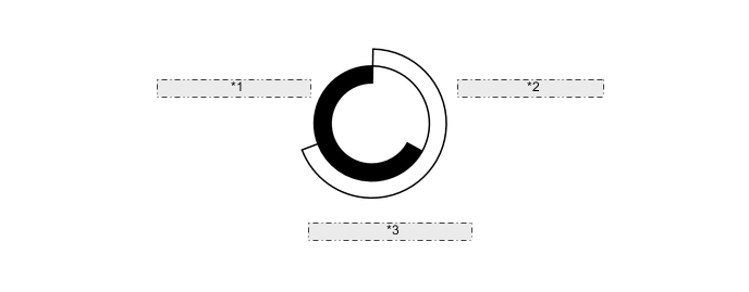
Figure 2. Operation Model Diagram: Upon Starting and

*1 Exhaust Valve Opening (Advanced Position) *2 Intake Valve Opening (Intermediate Position) *3 Ensuring Starting Ability Figure 3. Operation Model Diagram: At Partial

*1 Exhaust Valve Opening (Retarded Position) *2 Intake Valve Opening (Retarded Position) *3 Atkinson Cycle Figure 4. Operation Model Diagram: At Partial Load to Heavy

*1 Exhaust Valve Opening (Retarded Position) *2 Intake Valve Opening (Advanced Position) *3 Using Internal EGR or Improving Exhaust Ability
-
-
VVT-i Control
-
The Variable Valve Timing-intelligent (VVT-i) system is designed to control the exhaust camshaft within a range of 55° (of crankshaft angle) to provide valve timing that is optimally suited to the engine operating conditions. This improves torque in all speed ranges as well as increasing fuel economy, and reducing exhaust emissions.
-
The following effects can be achieved due to the advanced angle and retarded angle of the intake and exhaust valves.
Figure 5. Operation Model Diagram: Upon Starting and
*1 Exhaust Valve Opening (Advanced Position) *2 Intake Valve Opening (Intermediate Position) *3 Ensuring Starting Ability Figure 6. Operation Model Diagram: At Partial

*1 Exhaust Valve Opening (Retarded Position) *2 Intake Valve Opening (Retarded Position) *3 Atkinson Cycle Figure 7. Operation Model Diagram: At Partial Load to Heavy

*1 Exhaust Valve Opening (Retarded Position) *2 Intake Valve Opening (Advanced Position) *3 Using Internal EGR or Improving Exhaust Ability
-
-
Fuel Pump Control
-
The fuel pump is controlled by the ECM through the fuel pump control ECU assembly. Fuel pump control has a fuel cut control function. Fuel cut control stops the fuel pump when any of the SRS airbags has deployed.
-
-
Fuel Pump (for High Pressure) Control
-
The ECM performs variable control to achieve the high pressure fuel pressure in accordance with the driving conditions. A system that only discharges the necessary fuel amount via the spill control valve control has achieved drive torque reduction and reduced noise.
Control Pressure for Each Driving Condition Condition Control Pressure Idling 4.0 MPa Except Idling 4 to 20 MPa
-
-
Cooling Fan Control
-
The cooling fan control system achieves an optimal fan speed in accordance with the engine coolant temperature, vehicle speed, engine speed, and air conditioning operating conditions.
-
-
Cranking Hold Function
-
When the engine switch is pressed with the brake pedal depressed and the shift lever in P or N, this function operates the starter assembly until the engine starts. This prevents application of the starter assembly for an inadequate length of time. It also prevents the engine from being cranked after it has started.
-
-
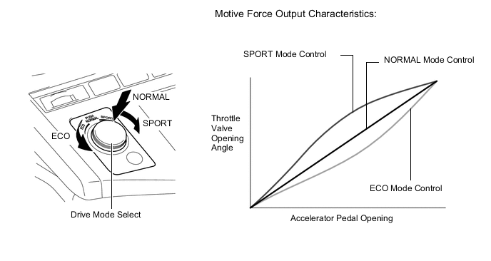
SPORT Mode and ECO Mode Control
-
During SPORT mode, the ECM optimizes acceleration feel by increasing the throttle valve opening angle more quickly at the beginning of accelerator pedal operation.
-
During ECO mode, the ECM optimizes fuel economy and driving performance by gently generating the motive force in comparison to accelerator pedal operation. At the same time, it supports ECO driving by optimizing the air conditioning performance.
-
-
Drive Start Control System
-
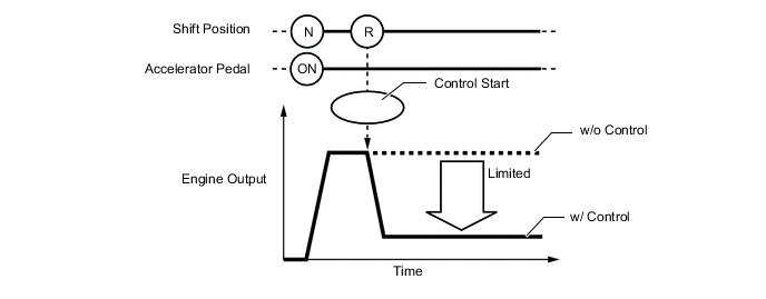
When abnormal driver accelerator pedal and shift operations are detected, the system limits the engine output and informs the driver.
Tech Tips
When the system is operating, even if the driver depresses and holds the accelerator pedal, engine output may increase on an uphill slope and decrease on a downhill slope. This behavior allows the system to restrict the vehicle speed and acceleration below the predetermined limit on slopes and is not a malfunction.
-
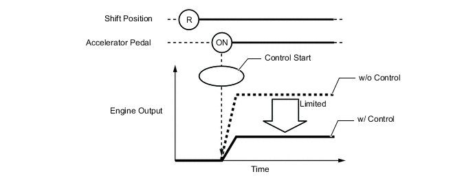
Control during Reverse Operation
-
Responds to excessive depression of the accelerator pedal while operating in reverse.
-
Corrects engine output according to the road grade and steering angle.
Control Start Conditions (When all of the following conditions are met, control starts.)
-
Shift position is R.
-
Accelerator pedal is depressed.
Control Operation Limits the engine output so the vehicle speed and acceleration are at or below a certain level. Control Stop Conditions
-
Shift position is not R.
-
Accelerator pedal is fully released.
-
-
-
Control during Manual Shift Operation
-
Responds to shift operations with the accelerator pedal depressed.
-
Changes the limit amount according to the manual shift operation pattern.
-
Corrects engine output according to the road grade and steering angle.
-
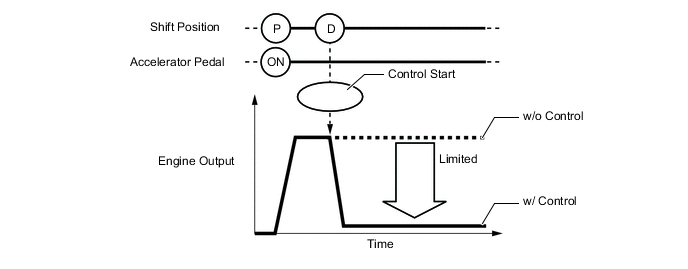
Control when Starting Off from a Parked Position
Control Start Conditions (When all of the following conditions are met, control starts.)
-
Shift position is changed from P to D, or P to R.
-
Accelerator opening angle is approximately 1/5 or higher.
Control Operation Limits the engine output so the vehicle speed and acceleration are at or below a certain level. Control Stop Conditions
-
Shift position is P or N.
-
Accelerator pedal is fully released.
-
-
Control when Starting Off from a Parked Position
Control Start Conditions (When all of the following conditions are met, control starts.)
-
Shift position is changed from R to D, D to R, or N to R.
-
Accelerator opening angle is approximately 1/5 or higher.
Control Operation Limits the engine output so the vehicle speed and acceleration are at or below a certain level. Control Stop Conditions
-
Shift position is P or N.
-
Accelerator pedal is fully released.
Tech Tips
-
The engine output restraint level differs in the above 2 situations.
-
During control while a manual shift operation is performed (from control start until the accelerator pedal is released), the system informs the driver of the control via the multi-information display. For details, refer to the combination meter assembly.
-
-
-
-
-
CONSTRUCTION
-
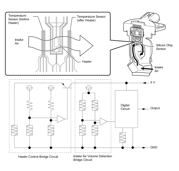
Mass Air Flow Meter Sub-assembly
-
The mass air flow meter sub-assembly, which is a slot-in type, allows a portion of the intake air to flow through the detection area.
-
This mass air flow meter sub-assembly has built-in intake air temperature sensors.
-
Intake air flows past the temperature sensor (before heater), the heater, and then the temperature sensor (after heater) of the silicon chip sensor in the by-pass duct. As the intake air is warmed up when it is exposed to the heater, the temperature of the intake air as it flows past the temperature sensor (after heater) is higher than when it flows past the temperature sensor (before heater). The difference in temperature of the intake air at each temperature sensor varies depending on the velocity of the intake air that flows past the silicon chip sensor. The temperature sensor bridge circuit detects the difference in temperature and the control circuit converts it into a pulse signal and outputs it to the ECM. When the temperature detected by the temperature sensor (before heater) is higher than that detected by the temperature sensor (after heater), backflow of the intake air is detected.
-
The ECM calculates the intake air volume based on the pulse signal received from the mass air flow meter sub-assembly, and uses it to determine the fuel injection duration necessary for an optimal air-fuel ratio.
-
The heater control bridge circuit has a temperature sensor and power transistor, and maintains the heater temperature at a specific temperature.
Tech Tips
When the DTC is stored, the ECM enters fail-safe mode. During fail-safe mode, the ECM calculates the fuel injection duration based on the engine speed and throttle valve angle. Fail-safe mode continues until a pass condition is detected. For details, refer to the Repair Manual.
-
-
Crankshaft Position Sensor
-
Magneto-Resistance Element (MRE) type crankshaft position sensor is used to detect the engine speed and crankshaft angle.
-
The crank angle sensor plate (timing rotor) of the crankshaft consists of 34 teeth with 2 teeth missing. The crankshaft position sensor outputs a crankshaft rotation signal every 10°, and the change of the signal due to the missing teeth is used to determine top-dead-center.
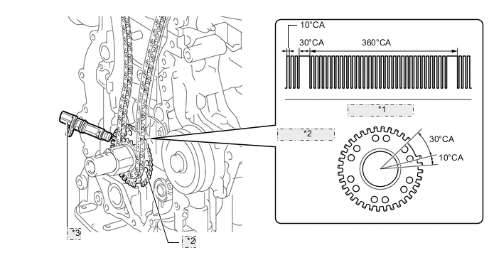
*1 Output Waveforms *2 Crank Angle Sensor Plate *3 Crankshaft Position Sensor
-
-
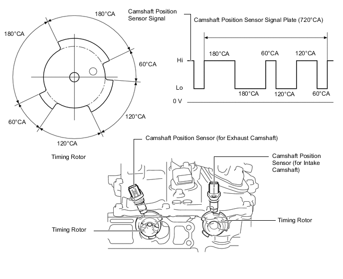
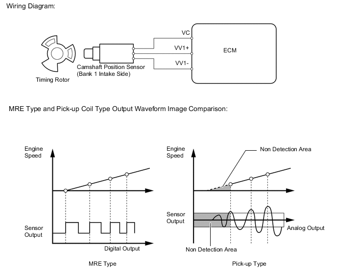
Camshaft Position Sensor
-
Magneto-Resistance Element (MRE) type camshaft position sensors (intake and exhaust) are used. To detect each camshaft position, a timing rotor that is secured to the camshaft is used to generate 3 pulses for every 2 revolutions of the crankshaft. The timing rotor for each camshaft is part of the respective camshaft.
-
An MRE type camshaft position sensor consists of an MRE, a magnet and a sensor. The direction of the magnetic field changes due to the profile (protruding and non-protruding portions) of the timing rotor, which passes by the sensor. As a result, the resistance of the MRE changes, and the output voltage to the ECM changes to high or low. The ECM detects the camshaft position based on this output voltage.
-
-
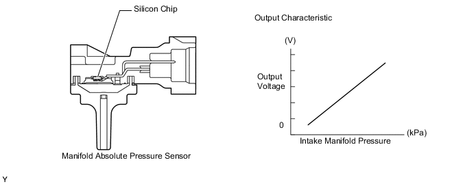
Manifold Absolute Pressure Sensor
-
The manifold absolute pressure sensor detects pressure inside the intake manifold as an absolute pressure with a built-in sensor and outputs a voltage. Based on the voltage from the manifold absolute pressure sensor, the ECM controls the air fuel ratio and EGR.
-
The manifold absolute pressure sensor consists of a silicon chip which utilizes the characteristics of a silicon chip that changes its electrical resistance when pressure is applied to it. The sensor converts the pressure into an electrical signal, and sends it to the ECM in an amplified form.
-
-
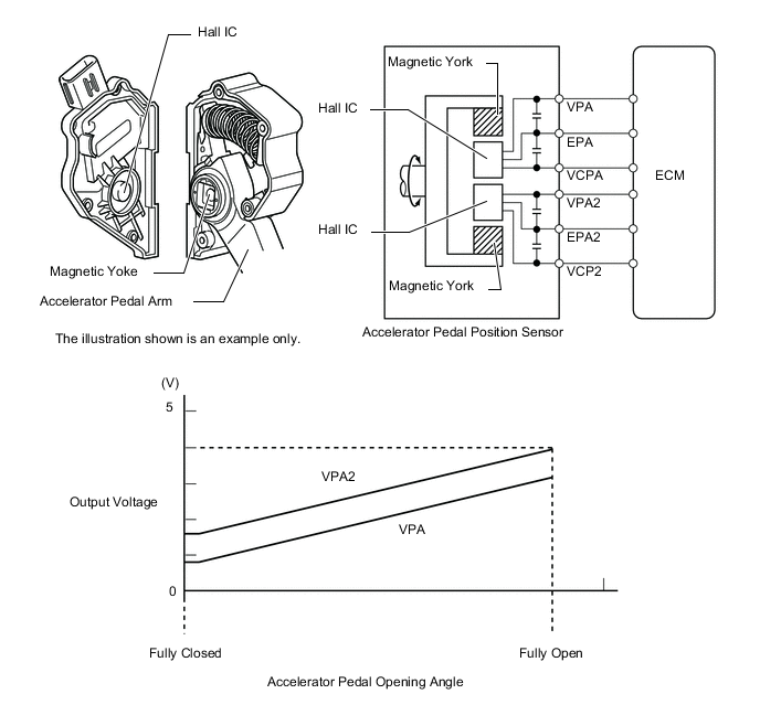
Accelerator Pedal Position Sensor
-
This non-contact type accelerator pedal position sensor uses a Hall IC, which is mounted on the accelerator pedal arm.
-
A magnetic yoke is mounted at the base of the accelerator pedal arm. This yoke rotates around the Hall IC in accordance with the amount of effort that is applied to the accelerator pedal. The Hall IC converts the changes in magnetic flux that occur into electrical signals, and outputs them in the form of accelerator pedal position signals to the ECM.
-
The Hall IC contains 2 circuits, one for the main signal, and one for the sub signal. It converts the accelerator pedal position (angle) into electric signals that have differing characteristics and outputs them to the ECM.
-
-
-
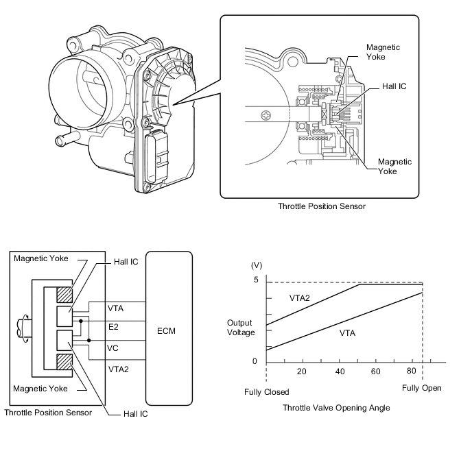
Throttle Position Sensor
-
This non-contact type throttle position sensor uses a Hall IC, which is mounted on the throttle body with motor assembly.
-
The Hall IC is surrounded by a magnetic yoke. The Hall IC converts the changes that occur in the magnetic flux into electrical signals, and outputs them in the form of throttle valve position signals to the ECM.
-
The Hall IC contains circuits for the main and sub signals. It converts the throttle valve opening angle into electric signals that have differing characteristics, and outputs them to the ECM.
-
-
-
Air Fuel Ratio Sensor
-
A planar type air fuel ratio sensor is used.
-
The planar type air fuel ratio sensor uses alumina, which excels in heat conductivity and electrical insulation, to integrate a sensor element with a heater, thus improving the warm-up performance of the sensor.
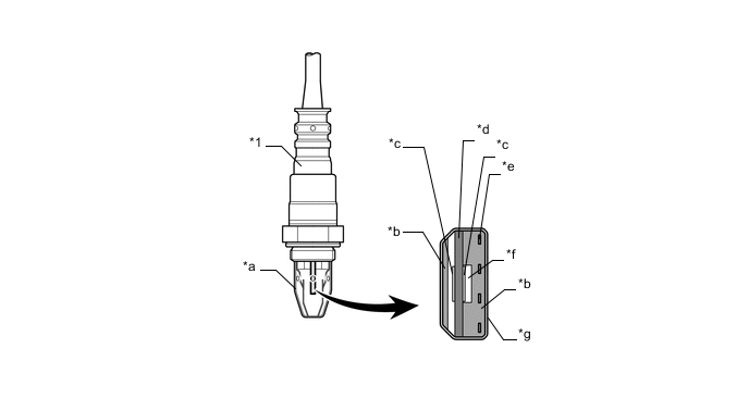
Text in Illustration *1 Air Fuel Ratio Sensor (Planar Type) - - *a Cover *b Alumina *c Platinum Electrode *d Sensor Element (Zirconia) *e Heater *f Atmosphere *g Coating (Ceramic) - - -
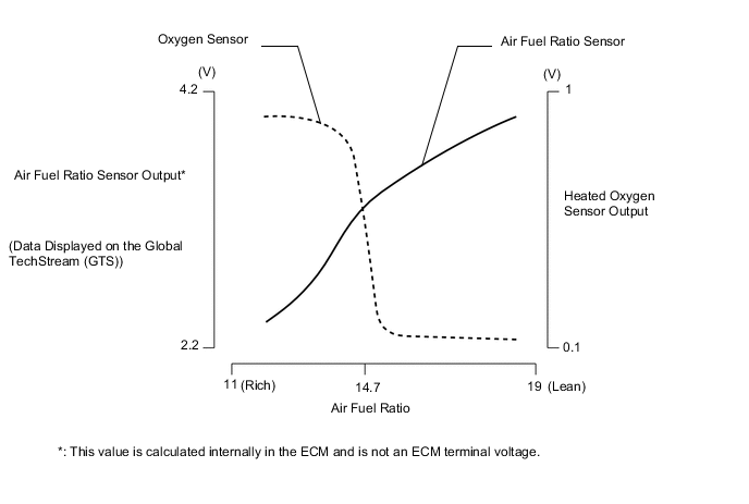
As illustrated below, a conventional heated oxygen sensor is characterized by a sudden change in its output voltage at the threshold of the stoichiometric air fuel ratio (14.7:1). In contrast, the air fuel ratio sensor data is approximately proportionate to the existing air fuel ratio. The air fuel ratio sensor converts the oxygen density into a voltage signal and sends it to the ECM. As a result, the detection precision of the air fuel ratio has been improved. Air fuel ratio sensor data can be viewed using the Global TechStream (GTS).
-
-
Heated Oxygen Sensor
-
The cup type heated oxygen sensor contains a sensor element that surrounds a heater.
-
The heated oxygen sensor is located behind the Three-Way Catalytic converter (TWC). The output voltage of the heated oxygen sensor changes in accordance with the heated oxygen concentration in the exhaust gas. The ECM uses this output voltage to determine whether the present air fuel ratio is richer or leaner than the stoichiometric air fuel ratio.
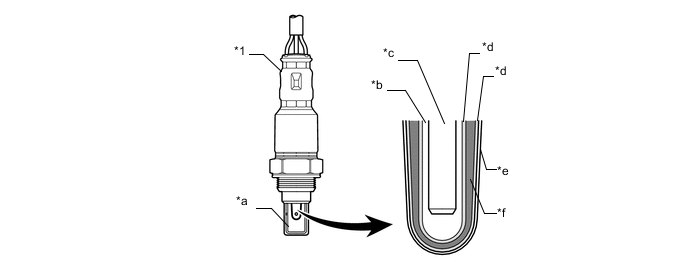
Text in Illustration *1 Heated Oxygen Sensor (Cup Type) - - *a Cover *b Atmosphere *c Heater *d Platinum Electrode *e Coating (Ceramic) *f Sensor Element (Zirconia)
-
-
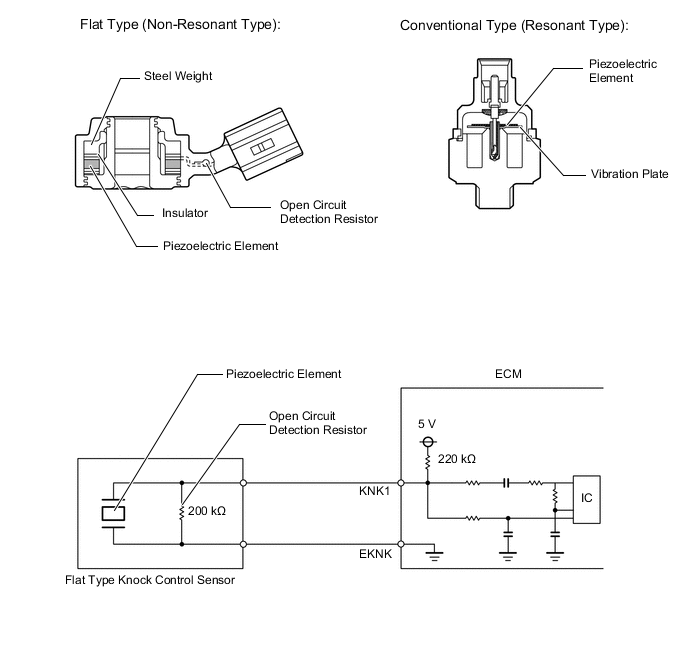
Knock Control Sensor
-
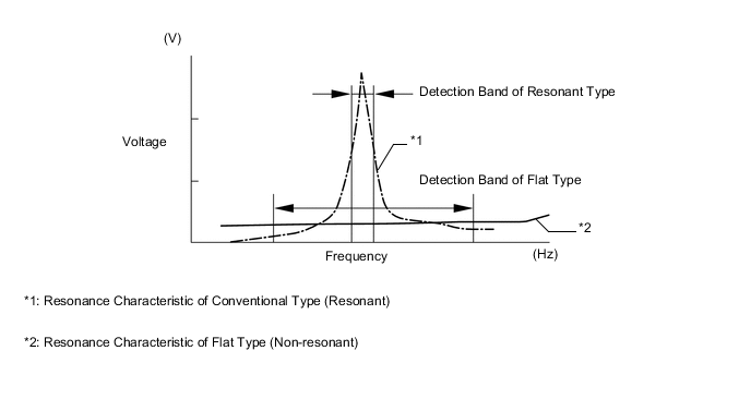
In a conventional knock control sensor (resonant type), a vibration plate is built into the sensor. This plate has the same resonance point as the knocking* frequency of the cylinder block sub-assembly. This sensor can only detect vibrations in this frequency band.
*: The term "knock" or "knocking" is used in this case to describe either preignition or detonation of the air fuel mixture in the combustion chamber. Preignition or detonation refers to the air fuel mixture being ignited earlier than is advantageous. This use of "knock" or "knocking" is not primarily used to refer to a loud mechanical noise that may be produced by an engine.
-
A flat type knock control sensor (non-resonant type) has the ability to detect vibrations in a wider frequency band (from about 5 to 15 kHz) and has the following features:
-
A flat type knock control sensor is installed to an engine by placing it over a stud bolt installed on the cylinder block sub-assembly. For this reason, a hole for the stud bolt exists in the center of the sensor.
-
In the sensor, a steel weight is located in the upper portion. An insulator is located between the weight and a piezoelectric element.
-
An open/short circuit detection resistor is integrated in the sensor.
-
-
The engine knocking frequency will vary slightly depending on the engine speed. The flat type knock control sensor can detect vibrations even when the engine knocking frequency changes. Due to the use of the flat type knock control sensor, the vibration detection ability is increased compared to a conventional type knock control sensor, and more precise ignition timing control is possible.
-
An open or short circuit detection resistor is integrated in the sensor. When the ignition is ON, the open circuit detection resistor in the knock control sensor and the resistor in the ECM keep the voltage at terminal KNK1 constant. An Integrated Circuit (IC) in the ECM constantly monitors the voltage of terminal KNK1. If an open or short circuit occurs between the knock control sensor and the ECM, the voltage of terminal KNK1 will change and the ECM will detect this and store a Diagnostic Trouble Code (DTC).
-
Vibrations caused by knocking are transmitted to the steel weight. The inertia of this weight applies pressure to the piezoelectric element. This action generates electromotive force.
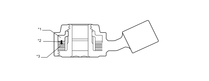
Text in Illustration *a Steel Weight *b Inertia *c Piezoelectric Element - -
-
-
Fuel Pressure Sensor
-
The fuel pressure sensor, which is mounted on the fuel delivery pipe sub-assembly, outputs a signal to the ECM that represents the fuel pressure in the fuel delivery pipe sub-assembly in order to allow the constant regulation of the fuel at an optimal pressure.
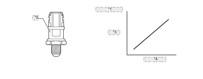
*1 Sensor Output Characteristics *2 Fuel Pressure Sensor *3 Voltage *4 Fuel Pressure
-
-
Oil Pressure Sender Gauge Assembly
-
The oil pressure sender gauge assembly consists of a semiconductor which utilizes the characteristics of a silicon chip that changes its electrical resistance when pressure is applied to it. The gauge converts the engine oil pressure into an electrical signal, and sends it to the ECM in an amplified form.
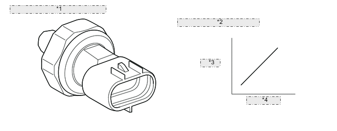
*1 Oil Pressure Sender Gauge Assembly *2 Sensor Output Characteristics *3 Voltage *4 Oil Pressure
-
-
Cam Timing Oil Control Solenoid Assembly
-
The cam timing oil control solenoid assembly for VVT-iW is installed to the timing chain cover assembly.
-
The oil passage of the oil control valve built inside the camshaft timing gear bolt is switched by controlling the shaft movement amount to achieve the optimal valve timing based on the duty signal from the ECM.
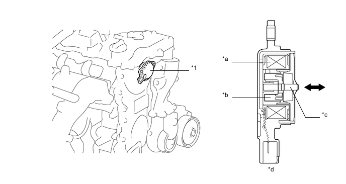
Text in Illustration *1 Cam Timing Oil Control Solenoid Assembly - - *a Solenoid Coil *b Plunger *c Shaft *d Cam Timing Oil Control Solenoid Assembly Cross Section
-
-
Camshaft Timing Oil Control Valve Assembly
-
The camshaft timing oil control valve assembly controls its spool valve using duty-cycle control from the ECM. This allows hydraulic pressure to be applied to the camshaft timing exhaust gear assembly advance or retard side. When the engine is stopped, the camshaft timing oil control valve assembly will move to the advance position.
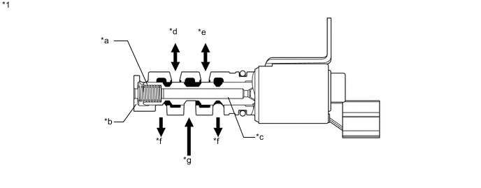
Text in Illustration *1 Camshaft Timing Oil Control Valve Assembly - - *a Spring *b Sleeve *c Spool Valve *d to Camshaft Timing Exhaust Gear Assembly (VVT-i Controller) (Advance Side) *e to Camshaft Timing Exhaust Gear Assembly (VVT-i Controller) (Retard Side) *f Drain *g Oil Pressure (from Oil Pump) - -
-
-
Ignition Coil Assembly
-
The Direct Ignition System (DIS) provides 4 ignition coil assemblies, 1 for each cylinder. The spark plug caps, which provide contact to the spark plugs, are integrated with the ignition coil assembly. Also, an igniter is enclosed to simplify the system.

Text in Illustration *1 Ignition Coil Assembly - - *a Igniter *b Iron Core *c Plug Cap *d Secondary Coil *e Primary Coil - -
-
-
Spark Plug Assembly
-
Long-reach type spark plugs are used. This type of spark plug allows the area of the cylinder head sub-assembly that receives the spark plugs to be made thicker. Thus, the cylinder head water jacket can be extended near the combustion chamber, which contributes to cooling performance.
-
The triple ground electrode type iridium-tipped spark plugs are used to achieve a 100000 km (62140 miles) maintenance interval. By making the tip of the electrode out of iridium, it is possible to achieve superior ignition performance and durability when compared to platinum-tipped spark plugs. Furthermore, two ground electrodes have been added to further enhance ignitability, wear resistance, and fouling resistance.
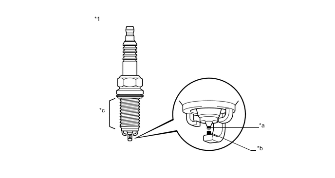
Text in Illustration *1 Spark Plug - - *a Iridium Tip *b Platinum Tip *c Long-reach - -
-
-
-
OPERATION
-
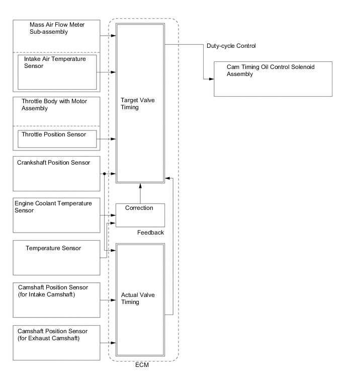
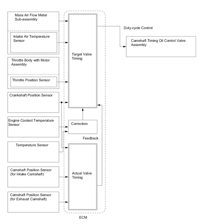
VVT-iW Control
-
Based on engine speed, intake air volume, throttle position and engine coolant temperature, the ECM calculates optimal valve timing for all driving conditions. The ECM also controls the cam timing oil control solenoid assembly. In addition, the ECM uses signals from the camshaft position sensors and the crankshaft position sensor to detect the actual valve timing, thus providing feedback control to achieve the target valve timing.
-
-
VVT-i Control
-
Based on engine speed, intake air volume, throttle position and engine coolant temperature, the ECM calculates optimal valve timing for all driving conditions. The ECM also controls the camshaft timing oil control valve assembly. In addition, the ECM uses signals from the camshaft position sensors and the crankshaft position sensor to detect the actual valve timing, thus providing feedback control to achieve the target valve timing.
-
-
Fuel Pump Control
-
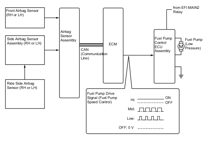
The ECM transmits a fuel pump operation request signal to the fuel pump control ECU assembly that corresponds to the engine operating conditions. Based on the signal received from the ECM, the fuel pump control ECU assembly controls the power supplied to the fuel pump in 3 levels (low, mid and high). Battery voltage is directly supplied to the fuel pump for the high level. However, the mid and low levels, Pulse Width Modulation (PWM) control is used to control the power supplied. This contributes to fuel economy by reducing current consumption compared to conventional control, which operates by switching a resistor in and out of the circuit.
-
The fuel pump control system has a fuel cut control function. Fuel cut control stops the fuel pump when any of the SRS airbags has deployed.
-
-
Cooling Fan Control
-
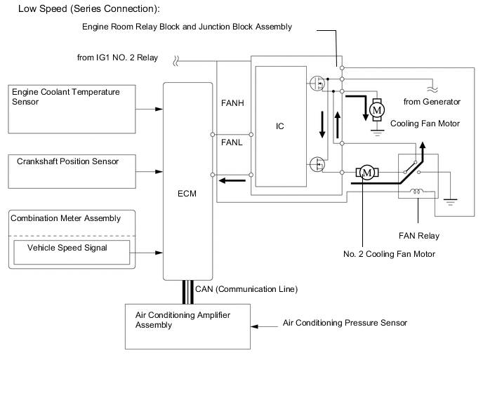
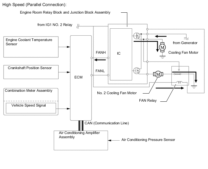
For the cooling fan control system, the ECM controls the cooling fan speed in accordance with the engine coolant temperature and the air conditioning operating conditions.
-
The ECM controls the cooling fan speed based on air conditioning pressure sensor signals and engine coolant temperature sensor signals. The air conditioning pressure sensor signals are sent from the air conditioning amplifier to the ECM. This control is accomplished by operating the 2 fan motors in 2 stages, at low speed (series connection) and high speed (parallel connection).
-
-
-
Cranking Hold Function
-
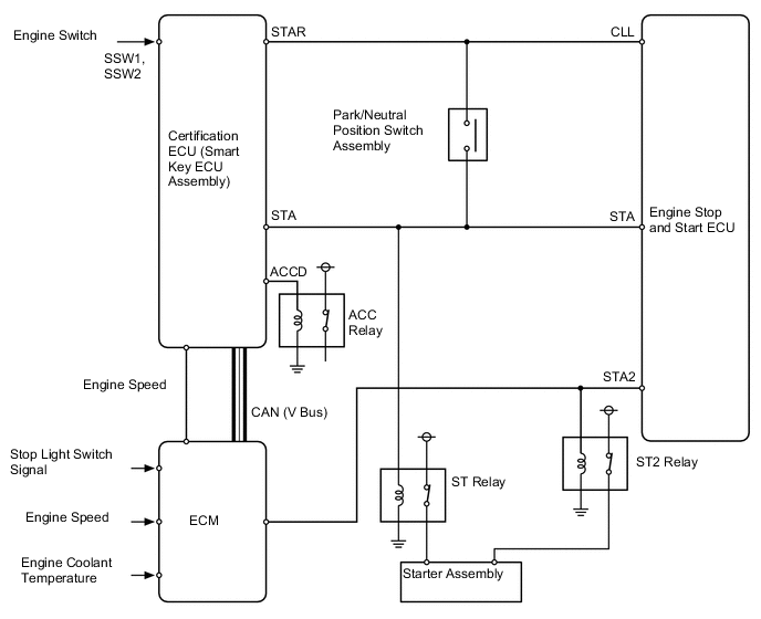
When first starting the engine, if the certification ECU (smart key ECU assembly) receives a start signal from the engine switch, the certification ECU (smart key ECU assembly) sends an operation signal to the ST relay via the park/neutral position switch assembly when the shift lever is in P or N and the engine stop and start ECU sends an operation signal to the STS relay to operate the starter assembly. At this time, the certification ECU (smart key ECU assembly) turns the ACC relay operation signal (ACCD) off to prevent flickering of the meter, clock and audio systems.
-
When starting the engine during idling stop control, the engine stop and start ECU sends operation signals to the ST relay and STS relay according to the vehicle condition to operate the starter assembly.
-
While the engine is cranking, the certification ECU (smart key ECU assembly) and/or engine stop and start ECU continues to send an operation signal to the starter relay until it has been detected that the engine has started successfully. Whether the engine has started successfully is determined by the certification ECU (smart key ECU assembly) and ECM, and once it has been determined that the engine has started successfully, the signal output to the certification ECU (smart key ECU assembly) and/or engine stop and start ECU to the starter relay is stopped.
-
The crank hold time and engine speed when it has been determined that the engine has started successfully are determined according to the engine coolant temperature.
-
-
-
FAIL-SAFE
-
When a malfunction of any of the sensors is detected, there is a possibility of an engine or other malfunction occurring if the ECM were to continue normal control. To prevent such a problem, the fail-safe function of the ECM either relies on the data stored in memory to allow the engine control system to continue operating, or stops the engine if a hazard is anticipated. For details, refer to the Repair Manual.
-
-
DIAGNOSIS
-
When the ECM detects a malfunction, the ECM records information related to the fault. Furthermore, the Malfunction Indicator Lamp (MIL) in the combination meter assembly illuminates or blinks to inform the driver.
-
The ECM also stores Diagnostic Trouble Codes (DTCs) for malfunctions it has detected. The DTCs can be accessed by using the Global TechStream (GTS).
-
For details, refer to the Repair Manual.
-