SFI SYSTEM(w/ Canister Pump Module) ACIS Control Circuit
DESCRIPTION
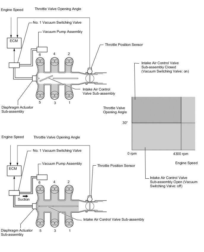
ACIS (Acoustic Control Induction System) controls the opening and closing the intake air control valve sub-assembly built into the intake air surge tank assembly to increase the intake efficiency according to the engine load.
When the engine speed is between 0 and 4300 rpm and the throttle valve opening angle is 30° or more, the ECM activates the No. 1 vacuum switching valve (for intake air control valve sub-assembly) which then applies vacuum from the vacuum pump assembly to the diaphragm actuator sub-assembly and closes the intake air control valve sub-assembly.
When the engine speed and/or throttle valve opening angle are not as specified above, the ECM deactivates the No. 1 vacuum switching valve (for intake air control valve sub-assembly), causing the intake air control valve sub-assembly to open.
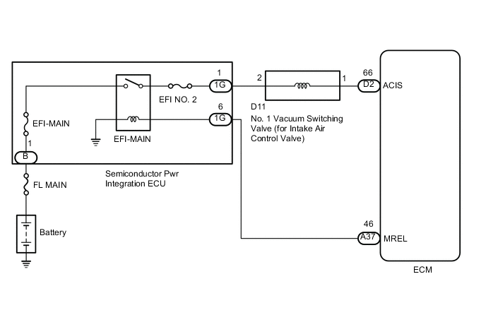
WIRING DIAGRAM
CAUTION / NOTICE / HINT
Note
Inspect the fuses for circuits related to this system before performing the following procedure.
PROCEDURE
-
PERFORM ACTIVE TEST USING GTS (ACTIVATE THE VSV FOR INTAKE CONTROL)
-
Connect the GTS to the DLC3.
-
Start the engine.
-
Turn the GTS on.
-
Enter the following menus: Powertrain / Engine / Active Test / Activate the VSV for Intake Control.
Powertrain > Engine > Active TestTester Display Activate the VSV for Intake Control -
According to the display on the GTS, perform the Active Test to operate the No. 1 vacuum switching valve (for intake air control valve sub-assembly) and check for the operating sound of the intake air control valve sub-assembly in the intake air surge tank assembly.
OK Operating noise can be heard. Result Proceed to OK NG
OK 
PROCEED TO NEXT SUSPECTED AREA SHOWN IN PROBLEM SYMPTOMS TABLE Click here
NG 
-
-
INSPECT INTAKE AIR SURGE TANK ASSEMBLY (INTAKE AIR CONTROL VALVE SUB-ASSEMBLY OPERATION)
-
Inspect the intake air surge tank assembly (intake air control valve sub-assembly).
Result Proceed to OK NG
NG
REPLACE INTAKE AIR SURGE TANK ASSEMBLY Click here
OK
-
-
INSPECT VACUUM HOSE SUB-ASSEMBLY (NO. 1 VACUUM SWITCHING VALVE (FOR INTAKE AIR CONTROL VALVE SUB-ASSEMBLY) - INTAKE AIR SURGE TANK ASSEMBLY)
-
Check the vacuum hose sub-assembly (No. 1 vacuum switching valve (for intake air control valve sub-assembly) - intake air surge tank assembly) for looseness, disconnection and blockage.
OK No looseness, disconnection or blockage. Result Proceed to OK NG
NG
REPAIR OR REPLACE VACUUM HOSE SUB-ASSEMBLY
OK
-
-
CHECK VACUUM
-
Disconnect the vacuum hose sub-assembly from the No. 1 vacuum switching valve (for intake air control valve sub-assembly).
-
Start the engine.
-
Use your finger to confirm that hose has suction.
Result Result Proceed to Suction applied A No suction B
B 
INSPECT VACUUM PUMP ASSEMBLY Click here
A
-
-
INSPECT NO. 1 VACUUM SWITCHING VALVE (FOR INTAKE AIR CONTROL VALVE SUB-ASSEMBLY)
-
Inspect the No. 1 vacuum switching valve (for intake air control valve sub-assembly).
Result Proceed to OK NG
NG
REPLACE NO. 1 VACUUM SWITCHING VALVE (FOR INTAKE AIR CONTROL VALVE SUB-ASSEMBLY) Click here
OK
-
-
CHECK TERMINAL VOLTAGE (POWER SOURCE OF NO. 1 VACUUM SWITCHING VALVE (FOR INTAKE AIR CONTROL VALVE SUB-ASSEMBLY))
-
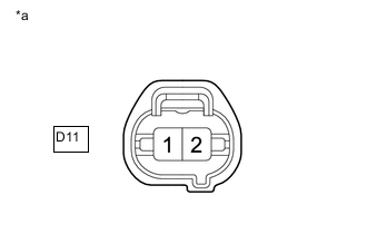
*a Front view of wire harness connector
(to No. 1 Vacuum Switching Valve (for Intake Air Control Valve Sub-assembly))
Disconnect the No. 1 vacuum switching valve (for intake air control valve sub-assembly) connector.
-
Turn the engine switch on (IG).
-
Measure the voltage according to the value(s) in the table below.
Standard Voltage Tester Connection Condition Specified Condition D11-2 - Body ground Engine switch on (IG) 11 to 14 V Result Proceed to OK NG
NG
CHECK HARNESS AND CONNECTOR (SEMICONDUCTOR PWR INTEGRATION ECU - NO. 1 VACUUM SWITCHING VALVE (FOR INTAKE AIR CONTROL VALVE SUB-ASSEMBLY)) Click here
OK
-
-
CHECK HARNESS AND CONNECTOR (NO. 1 VACUUM SWITCHING VALVE (FOR INTAKE AIR CONTROL VALVE SUB-ASSEMBLY) - ECM)
-
Disconnect the No. 1 vacuum switching valve (for intake air control valve sub-assembly) connector.
-
Disconnect the ECM connector.
-
Measure the resistance according to the value(s) in the table below.
Standard Resistance Tester Connection Condition Specified Condition D11-1 - D2-66 (ACIS) Always Below 1 Ω D11-1 or D2-66 (ACIS) - Body ground and other terminals Always 10 kΩ or higher Result Proceed to OK NG
OK
REPLACE ECM Click here
NG
REPAIR OR REPLACE HARNESS OR CONNECTOR
-
-
CHECK HARNESS AND CONNECTOR (SEMICONDUCTOR PWR INTEGRATION ECU - NO. 1 VACUUM SWITCHING VALVE (FOR INTAKE AIR CONTROL VALVE SUB-ASSEMBLY))
-
Disconnect the semiconductor pwr integration ECU connector.
-
Disconnect the No. 1 vacuum switching valve (for intake air control valve sub-assembly) connector.
-
Measure the resistance according to the value(s) in the table below.
Standard Resistance Tester Connection Condition Specified Condition 1G-1 - D11-2 Always Below 1 Ω 1G-1 or D11-2 - Body ground and other terminals Always 10 kΩ or higher Result Proceed to OK NG
OK
GO TO ECM POWER SOURCE CIRCUIT Click here
NG
REPAIR OR REPLACE HARNESS OR CONNECTOR
-
-
INSPECT VACUUM PUMP ASSEMBLY
-
Inspect the vacuum pump assembly.
Result Proceed to OK NG
OK
REPAIR OR REPLACE VACUUM HOSE SUB-ASSEMBLY (NO. 1 VACUUM SWITCHING VALVE (FOR INTAKE AIR CONTROL VALVE SUB-ASSEMBLY) - VACUUM PUMP ASSEMBLY)
NG
REPLACE VACUUM PUMP ASSEMBLY Click here
-