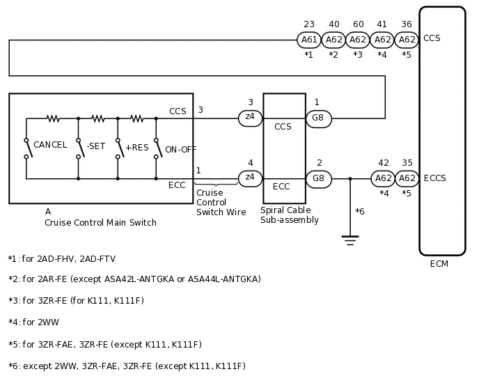
CRUISE CONTROL SYSTEM Cruise Control Switch Circuit
| DTC Code | DTC Name |
|---|---|
| Cruise Control Switch Circuit |
DESCRIPTION
This circuit sends a signal to the ECM depending on the cruise control main switch condition. The battery supplies positive (+) battery voltage to the circuit control main switch. Then terminal CCS of the ECM receives the voltage according to the switch condition.
WIRING DIAGRAM
PROCEDURE
READ VALUE USING GTS
Check the Data List for proper functioning of the cruise control switch.
for 2AD-FTV, 2AD-FHV:
Powertrain > Cruise Control > Data List
Tester Display
Measurement Item
Range
Normal Condition
Diagnostic Note
CCS Main SW M-CPU
Cruise control switch signal (Main CPU)
ON or OFF
ON: Cruise control switch on
OFF: Cruise control switch off
-
Cancel Switch
CANCEL switch signal
ON or OFF
ON: CANCEL switch on
OFF: CANCEL switch off
-
SET/COAST Switch
-SET switch signal
ON or OFF
ON: -SET switch on
OFF: -SET switch off
-
RES/ACC Switch
+RES switch signal
ON or OFF
ON: +RES switch on
OFF: +RES switch off
-
Powertrain > Cruise Control > Data List
Tester Display
CCS Main SW M-CPU
Cancel Switch
SET/COAST Switch
RES/ACC Switch
OK
When the cruise control switch is operated, the display changes as shown above.
for 2AR-FE, 3ZR-FE, 3ZR-FAE:
Powertrain > Cruise Control > Data List
Tester Display
Measurement Item
Range
Normal Condition
Diagnostic Note
Cancel Switch
CANCEL switch status
ON or OFF
ON: CANCEL switch on
OFF: CANCEL switch off
-
-SET Switch
-SET switch status
ON or OFF
ON: -SET switch on
OFF: -SET switch off
-
+RES Switch
+RES switch status
ON or OFF
ON: +RES switch on
OFF: +RES switch off
-
Cruise Ready Main-CPU
Cruise control system standby condition
ON or OFF
Each time cruise control switch is pushed, ON or OFF changes
-
Cruise Ready Sub-CPU
Cruise control system standby condition
ON or OFF
Each time cruise control switch is pushed, ON or OFF changes
-
Powertrain > Cruise Control > Data List
Tester Display
Cancel Switch
-SET Switch
+RES Switch
Cruise Ready Main-CPU
Cruise Ready Sub-CPU
OK
When the cruise control switch is operated, the display changes as shown above.
for 2WW:
Powertrain > Cruise Control > Data List
Tester Display
Measurement Item
Range
Normal Condition
Diagnostic Note
CANCEL SW
CANCEL switch signal
ON or OFF
ON: CANCEL switch on
OFF: CANCEL switch off
-
-SET SW
-SET switch signal
ON or OFF
ON: -SET switch on
OFF: -SET switch off
-
+RES SW
+RES switch signal
ON or OFF
ON: +RES switch on
OFF: +RES switch off
-
Cruise Control Switch
Cruise control switch signal
ON or OFF
ON: Cruise control switch (ON/OFF) pushed
OFF: Cruise control switch (ON/OFF) released
-
Powertrain > Cruise Control > Data List
Tester Display
CANCEL SW
-SET SW
+RES SW
Cruise Control Switch
OK
When the cruise control switch is operated, the display changes as shown above.
Result
Proceed to
OK
NG
INSPECT CRUISE CONTROL MAIN SWITCH
Remove the cruise control main switch.
Inspect the cruise control main switch.
Result
Proceed to
OK
NG
CHECK CRUISE CONTROL SWITCH WIRE
Disconnect the z4 spiral cable sub-assembly connector.
Disconnect the A cruise control switch wire connector.
-
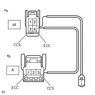
*a
Front view of wire harness connector
(to Spiral Cable Sub-assembly)
*b
Front view of wire harness connector
(to Cruise Control Switch)
except ASA42L-ANTGKA or ASA44L-ANTGKA:
Measure the resistance according to the value(s) in the table below.
Standard Resistance
Tester Connection
Condition
Specified Condition
z4-3 (CCS) - A-3 (CCS)
Always
Below 1 Ω
z4-4 (ECC) - A-1 (ECC)
Always
Below 1 Ω
z4-3 (CCS) or A-3 (CCS) - Body ground
Always
10 kΩ or higher
z4-4 (ECC) or A-1 (ECC) - Body ground
Always
10 kΩ or higher
-
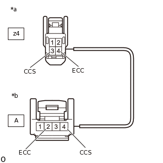
*a
Front view of wire harness connector
(to Spiral Cable Sub-assembly)
*b
Front view of wire harness connector
(to Cruise Control Main Switch)
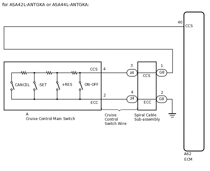
for ASA42L-ANTGKA or ASA44L-ANTGKA:
Measure the resistance according to the value(s) in the table below.
Standard Resistance
Tester Connection
Condition
Specified Condition
z4-3 (CCS) - A-4 (CCS)
Always
Below 1 Ω
z4-4 (ECC) - A-2 (ECC)
Always
Below 1 Ω
z4-3 (CCS) or A-4 (CCS) - Body ground
Always
10 kΩ or higher
z4-4 (ECC) or A-2 (ECC) - Body ground
Always
10 kΩ or higher
Result
Proceed to
OK
NG
NG REPLACE CRUISE CONTROL SWITCH WIRE
INSPECT SPIRAL CABLE SUB-ASSEMBLY
Remove the spiral cable sub-assembly.
for Single Type:Click here
for Dual Type:Click here
Inspect the spiral cable sub-assembly.
for Single Type:Click here
for Dual Type:Click here
Result
Proceed to
OK
NG
CHECK HARNESS AND CONNECTOR (SPIRAL CABLE SUB-ASSEMBLY - ECM AND BODY GROUND)
for 2AD-FHV, 2AD-FTV:
Disconnect the G8 spiral cable sub-assembly connector.
Disconnect the A61 ECM connector.
Measure the resistance according to the value(s) in the table below.
Standard Resistance
Tester Connection
Condition
Specified Condition
G8-1 (CCS) - A61-23 (CCS)
Always
Below 1 Ω
G8-2 (ECC) - Body ground
Always
Below 1 Ω
G8-1 (CCS) or A61-23 (CCS) - Body ground
Always
10 kΩ or higher
for 2AR-FE:
Disconnect the G8 spiral cable sub-assembly connector.
Disconnect the A62 ECM connector.
Measure the resistance according to the value(s) in the table below.
Standard Resistance
Tester Connection
Condition
Specified Condition
G8-1 (CCS) - A62-40 (CCS)
Always
Below 1 Ω
G8-2 (ECC) - Body ground
Always
Below 1 Ω
G8-1 (CCS) or A62-40 (CCS) - Body ground
Always
10 kΩ or higher
for 3ZR-FE (for K111, K111F):
Disconnect the G8 spiral cable sub-assembly connector.
Disconnect the A62 ECM connector.
Measure the resistance according to the value(s) in the table below.
Standard Resistance
Tester Connection
Condition
Specified Condition
G8-1 (CCS) - A62-60 (CCS)
Always
Below 1 Ω
G8-2 (ECC) - Body ground
Always
Below 1 Ω
G8-1 (CCS) or A62-60 (CCS) - Body ground
Always
10 kΩ or higher
for 3ZR-FAE, 3ZR-FE (except K111, K111F):
Disconnect the G8 spiral cable sub-assembly connector.
Disconnect the A62 ECM connector.
Measure the resistance according to the value(s) in the table below.
Standard Resistance
Tester Connection
Condition
Specified Condition
G8-1 (CCS) - A62-36 (CCS)
Always
Below 1 Ω
G8-2 (ECC) - A62-35 (ECCS)
Always
Below 1 Ω
G8-1 (CCS) or A62-36 (CCS) - Body ground
Always
10 kΩ or higher
for 2WW:
Disconnect the G8 spiral cable sub-assembly connector.
Disconnect the A62 ECM connector.
Measure the resistance according to the value(s) in the table below.
Standard Resistance
Tester Connection
Condition
Specified Condition
G8-1 (CCS) - A62-41 (CCS)
Always
Below 1 Ω
G8-2 (ECC) - A62-42 (ECCS)
Always
Below 1 Ω
G8-1 (CCS) or A62-41 (CCS) - Body ground
Always
10 kΩ or higher
Result
Proceed to
OK
NG
OK REPLACE ECM
for 2AD-FHV:Click here
for 2AD-FTV:Click here
for 2AR-FE:Click here
for 3ZR-FAE:Click here
for 3ZR-FE:Click here
for 2WW:Click here
NG REPAIR OR REPLACE HARNESS OR CONNECTOR