ENGINE IMMOBILISER SYSTEM(w/o Entry and Start System), Diagnostic DTC:B2780
| DTC Code | DTC Name |
|---|---|
| B2780 | Push Switch / Key Unlock Warning Switch Malfunction |
DESCRIPTION
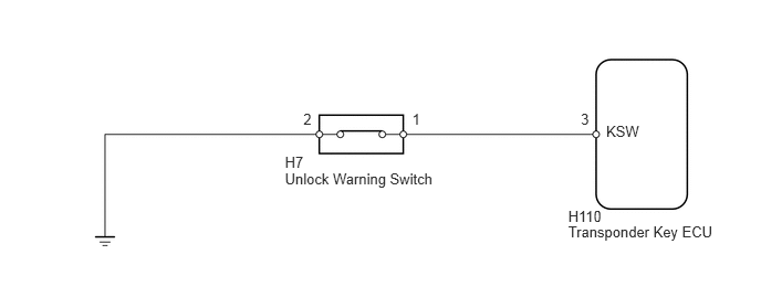
This DTC is stored if the transponder key ECU does not detect that the unlock warning switch is on even when the ignition switch is ON. Under normal conditions, the unlock warning switch is on when the ignition switch is ON.
DTC Code |
DTC Detection Condition |
Trouble Area |
|---|---|---|
B2780 |
The unlock warning switch is not detected as being on when the ignition switch is ON. |
|
WIRING DIAGRAM
CAUTION / NOTICE / HINT
When the transponder key ECU is replaced, reregister the ECU - ECM communication ID.
PROCEDURE
CLEAR DTC
Clear the DTCs (Click here).
CHECK FOR DTC
Check for DTCs (Click here).
OK
DTC B2780 is not output.
INSPECT UNLOCK WARNING SWITCH
-
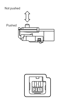
Remove the unlock warning switch (Click here).
Measure the resistance according to the value(s) in the table below.
Standard Resistance
Tester Connection
Switch Condition
Specified Condition
1 - 2
Pushed
Below 1 Ω
Not pushed
10 kΩ or higher
-
CHECK HARNESS AND CONNECTOR (UNLOCK WARNING SWITCH - BODY GROUND)
-
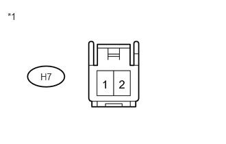
Disconnect the H7 switch connector.
Measure the resistance according to the value(s) in the table below.
Standard Resistance
Tester Connection
Condition
Specified Condition
H7-2 - Body ground
Always
Below 1 Ω
Table 1. Text in Illustration *1
Front view of wire harness connector
(to Unlock Warning Switch)
REPAIR OR REPLACE HARNESS OR CONNECTOR
-
CHECK HARNESS AND CONNECTOR (UNLOCK WARNING SWITCH - TRANSPONDER KEY ECU)
-
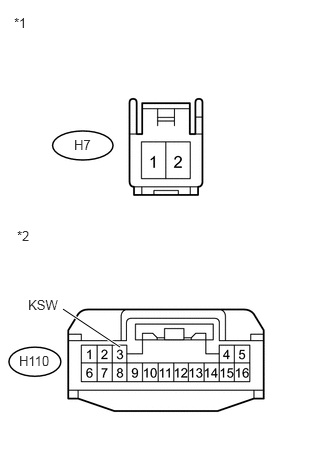
Disconnect the H7 switch connector.
Disconnect the H110 ECU connector.
Measure the resistance according to the value(s) in the table below.
Standard Resistance
Tester Connection
Condition
Specified Condition
H110-3 (KSW) - H7-1
Always
Below 1 Ω
H110-3 (KSW) or H7-1 - Body ground
Always
10 kΩ or higher
Table 2. Text in Illustration *1
Front view of wire harness connector
(to Unlock Warning Switch)
*2
Front view of wire harness connector
(to Transponder Key ECU)
REPLACE TRANSPONDER KEY ECU
REPAIR OR REPLACE HARNESS OR CONNECTOR
-