SFI SYSTEM, Diagnostic DTC:P0327 and P0328
| DTC Code | DTC Name |
|---|---|
| P0327 | Knock Sensor 1 Circuit Low Input (Bank 1 or Single Sensor) |
| P0328 | Knock Sensor 1 Circuit High Input (Bank 1 or Single Sensor) |
DESCRIPTION
The flat type knock control sensor (non-resonant type) has a structure that can detect vibration in a wider band of frequencies, from approximately 5 to 15 kHz, and has the following features:
The knock control sensor is fitted on the cylinder block to detect engine knocking.
The sensor contains a piezoelectric element which generates a voltage when it becomes deformed.
This occurs when the cylinder block vibrates due to knocking. If engine knocking occurs, the ignition timing is retarded to suppress it.
DTC No. |
Detection Item |
DTC Detection Condition |
Trouble Area |
MIL |
Memory |
|---|---|---|---|---|---|
P0327 |
Knock Sensor 1 Circuit Low Input (Bank 1 or Single Sensor) |
|
|
Comes on |
DTC stored |
P0328 |
Knock Sensor 1 Circuit High Input (Bank 1 or Single Sensor) |
At least 15 seconds after engine was started, at engine speed higher than 680 rpm, knock control sensor output voltage is higher than standard (3 trip detection logic). |
|
Comes on |
DTC stored |
If the ECM detects DTC P0327 and P0328, it enters fail-safe mode in knock feedback control operation condition (engine load is 40% or higher and engine coolant temperature is 40°C (104°F)).
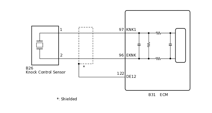
WIRING DIAGRAM
CONFIRMATION DRIVING PATTERN
When performing the confirmation driving pattern, obey all speed limits and traffic laws.
DTC P0327 and P0328 are detected when the vehicle is driven at approximately 100 km/h (62 mph) for 1 minute or more (at an engine speed of 1800 rpm or more, with an engine load of 40% or more after warm-up.
CAUTION / NOTICE / HINT
Read freeze frame data using the GTS. Freeze frame data records the engine condition when malfunctions are detected. When troubleshooting, freeze frame data can help determine if the vehicle was moving or stationary, if the engine was warmed up or not, if the air fuel ratio was lean or rich, and other data from the time the malfunction occurred.
PROCEDURE
CHECK HARNESS AND CONNECTOR (ECM - KNOCK CONTROL SENSOR)
Disconnect the ECM connector.
Disconnect the knock control sensor connector.
Measure the resistance according to the value(s) in the table below.
Standard Resistance
Tester Connection
Condition
Specified Condition
B31-97 (KNK1) - B26-1
Always
Below 1 Ω
B31-96 (EKNK) - B26-2
Always
Below 1 Ω
B31-97 (KNK1) or B26-1 - Body ground
Always
10 kΩ or higher
B31-96 (EKNK) or B26-2 - Body ground
Always
10 kΩ or higher
Result
Proceed to
OK
NG
NG REPAIR OR REPLACE HARNESS OR CONNECTOR
CHECK KNOCK CONTROL SENSOR INSTALLATION
Check the knock control sensor installation condition.
OK
Knock control sensor is installed correctly.
Result
Proceed to
OK
NG
REPLACE KNOCK CONTROL SENSOR
Replace the knock control sensor.
Result
Proceed to
NEXT
CHECK WHETHER DTC OUTPUT RECURS (DTC P0327 OR P0328)
Connect the GTS to the DLC3.
Turn the ignition switch to ON.
Turn the GTS on.
Clear the DTCs.
Powertrain > Engine and ECT > Clear DTCs
Turn the ignition switch off and wait for at least 30 seconds.
Start the engine and warm it up.
Turn the GTS on.
Drive the vehicle in accordance with the driving pattern described in Confirmation Driving Pattern.
Enter the following menus: Powertrain / Engine and ECT / Trouble Codes.
Read the pending DTCs.
Powertrain > Engine and ECT > Trouble Codes
Result
Result
Proceed to
DTC P0327 or P0328 is output
A
DTCs are not output
B
B END